6
install unit in system where voltage may fluctuate above or below
permissible limits.
NOTE: Use copper wire only between disconnect switch and unit.
NOTE: Install branch circuit disconnect of adequate size per NEC
to handle unit starting current. Locate disconnect within sight from
and readily accessible from unit, per Section 440--14 of NEC.
Route Ground and Power Wires
Remove access panel to gain access to unit wiring. Extend wires
from disconnect through power wiring hole provided and into unit
control box.
!
WARNING
ELECTRICAL SHOCK HAZARD
Failure to follow this warning could result in personal injury
or death.
The unit cabinet must have an uninterrupted or unbroken
ground to minimize personal injury if an electrical fault
should occur. The ground may consist of electrical wire or
metal conduit when installed in accordance with existing
electrical codes.
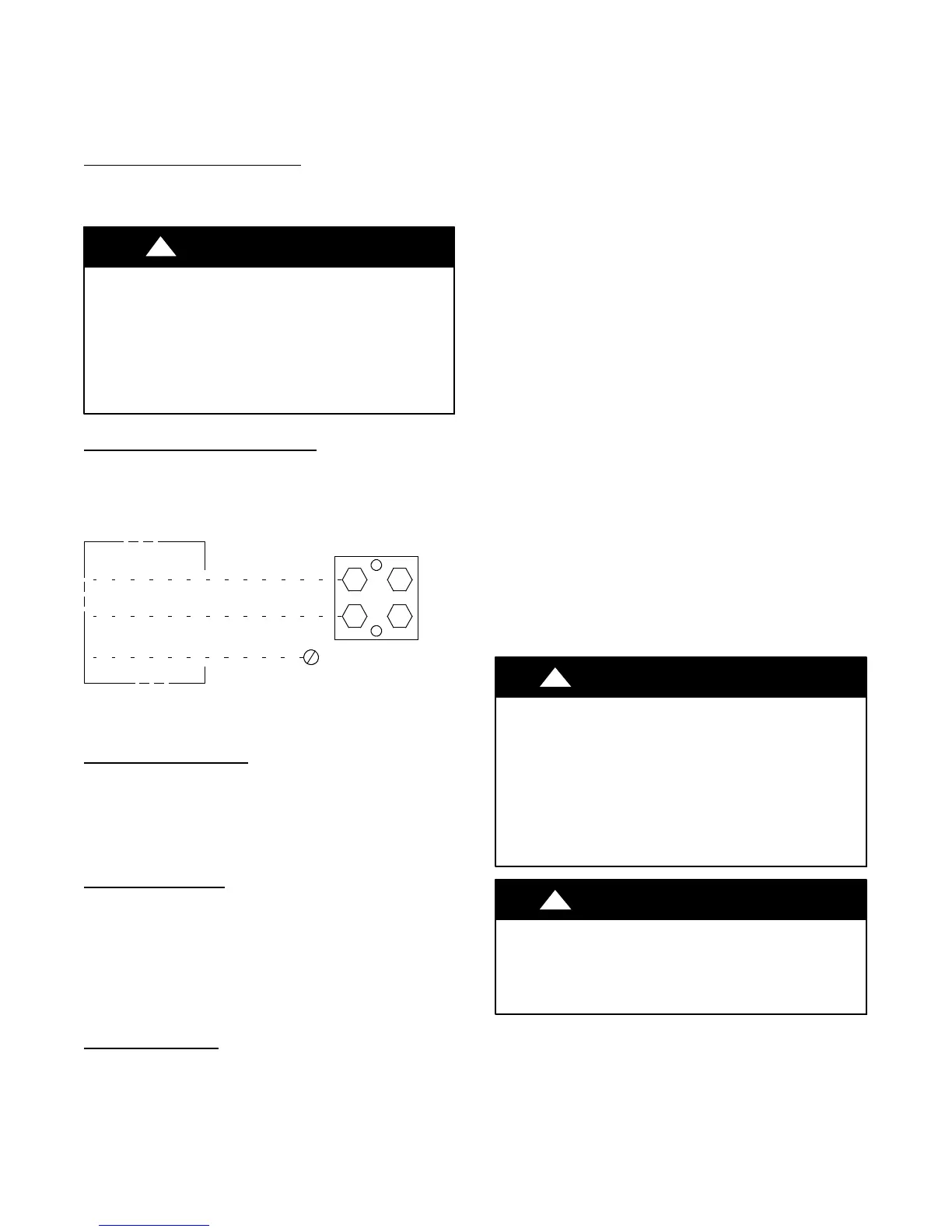
Connect Ground and Power Wires
Connect ground wire to ground connection in control box for
safety. Connect power wiring to contactor as shown in Fig. 6.
DISCONNECT
PER N. E. C. AND/OR
LOCAL CODES
CONTACTOR
GROUND
LUG
FIELD GROUND
WIRING
FIELD POWER
WIRING
A91056
Fig. 6 -- Line Power Connections
Connect Control Wiring
Connect to Evolution connections. Only two wires (AB) to
Evolution capable indoor unit (furnace or fan coil) is required.
Typical 4 wire (ABCD) may be connected (see Fig. 14).
IMPORTANT: This system requires the power supply to the
outdoor unit, and the indoor unit, for the wall control to
communicate with the outdoor unit.
General Information
Use No. 18 AWG or larger color-- coded, insulated (35C
minimum) wire for low voltage control wires.
All wiring must be NEC Class 2 and must be separated from
incoming power leads.
Use furnace transformer, fan coil transformer, or accessory
transformer for control power requirement of system accessories
external to the OD unit. The outdoor unit has its own transformer
power.
Final Wiring Check
IMPORTANT: Check factory wiring and field wire connections to
ensure terminations are secured properly. Check wire routing to
ensure wires are not in contact with tubing, sheet metal, etc.
Step 8 — Compressor Crankcase Heater
This compressor has an internal crankcase heater. Furnish power
to the unit a minimum of 24 hr before starting the unit for the first
time.
To furnish power to heater only, set thermostat to OFF and close
electrical disconnect to outdoor unit.
Power is not required to the indoor unit or wall control for proper
operation of heater. Crankcase heater will however be intelligently
energized as needed between operations, and otherwise even when
the wall control and indoor unit is not installed, as long as there is
power to the outdoor unit even if the indoor unit and wall control
are not yet installed.
Airflow Setup for Evolution Control Furnace or
FE Fan Coil (communicating)
This system can only be installed with Evolution--capable indoor
and Evolution wall control with the latest version software. When
using an Evolution wall control, airflow is automatically selected
based on equipment size. The user has the option of selecting
Comfort, Efficiency and Max airflow for Heating and/or Cooling
modes. These should be selected based on balance between the
homeowner’s comfort and energy consumption expectations. See
wall control Installation Instructions for additional available
adjustments.
Due to using a communicating control with the fan coil or the
furnace, dip switch adjustments are not necessary. The outdoor
unit configuration and the indoor airflows are determined by
communicating control setup.
Step 9 — Install Accessories
There are no refrigeration circuit or electrical accessories required
or available for installation within the unit. External to the unit, the
same accessories such as support feet, snow rack, wind baffle etc.,
are available on other Bryant units can also be used on this line of
product. Refer to the individual Installation Instructions packaged
with kits or accessories when installing.
Step 10 — Start--Up
CAUTION
!
UNIT OPERATION AND SAFETY HAZARD
Failure to follow this caution may result in minor personal
injury, equipment damage or improper operation.
Observe the following:
1. Do not overcharge system with refrigerant.
2. Do not operate unit in a vacuum or at negative pressure.
3. Do not disable low pressure switch
4. Dome temperatures may be hot.
CAUTION
!
PERSONAL INJURY HAZARD
Failure to follow this caution may result in personal injury.
Wear safety glasses, protective clothing, and gloves when
handling refrigerant.