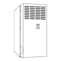
3
A
[736.9]
29
Ø7/8
[22.2]
ACCESSORY
5 15/16
[150.7]
28.39
[721.2]
Ø7/8
[22.2]
ACCESSORY
14 7/8
[337.3]
(BOTH SIDES)
Ø7/8
[22.2]
ACCESSORY
Ø7/8
[22.2]
ACCESSORY
Ø1 3/4
[44.5]
GAS ENTRY
Ø1/2
[12.7]
THERMOSTAT WIRE ENTRY
22 1/16
[560]
SIDE INLET
(BOTH SIDES)
11 7/16
[290.7]
9 11/16
[245.4]
[197.8]
7 13/16
Ø7/8
[22.2]
J.BOX PROVISION
Ø7/8
[22.2]
JUNCTION BOX
LOCATION
Ø1 3/4
[44.5]
GAS ENTRY
1 15/16
[49.2]
[25.4]
1 1/4
[31.8]
29 9/16
[750.7]
1 15/16
[49.2]
5 5/8
[143.3]
5 7/16
[138.5]
6 13/16
[172.3]
Ø1/2
[12.7]
THERMOSTAT WIRE ENTRY
19
[481.7]
OUTLET
21.6
[549.5]
BOTTOM INLET
33 1/4
[843.9]
9 9/16
[243.3]
3/4
[19.1]
5 7/8
[148.5]
3 7/16
[86.8]
9 7/8
[250.7]
27 3/4
[704.7]
2 5/16
[59]
FRONT OF CASING
TOP OF CASING
4 13/16
[122.2]
27 3/4
[704.7]
5 7/8
[148.5]
8 5/8
[219]
5 1/2
[140.3]
8 7/16
[213.5]
FRONT OF CASING
TOP OF CASING
6.1
[155.7]
2 1/16
[51.6]
5.1
[130.5]
1.7
[43.5]
Ø7/8
[22.2]
ACCESSORY (2)
AIR FLOW
AIR FLOW
BOTTOM RETURN
WIDTH
AIR FLOW
KNOCK OUTS FOR
VENTING(5
PLACES)
A10290
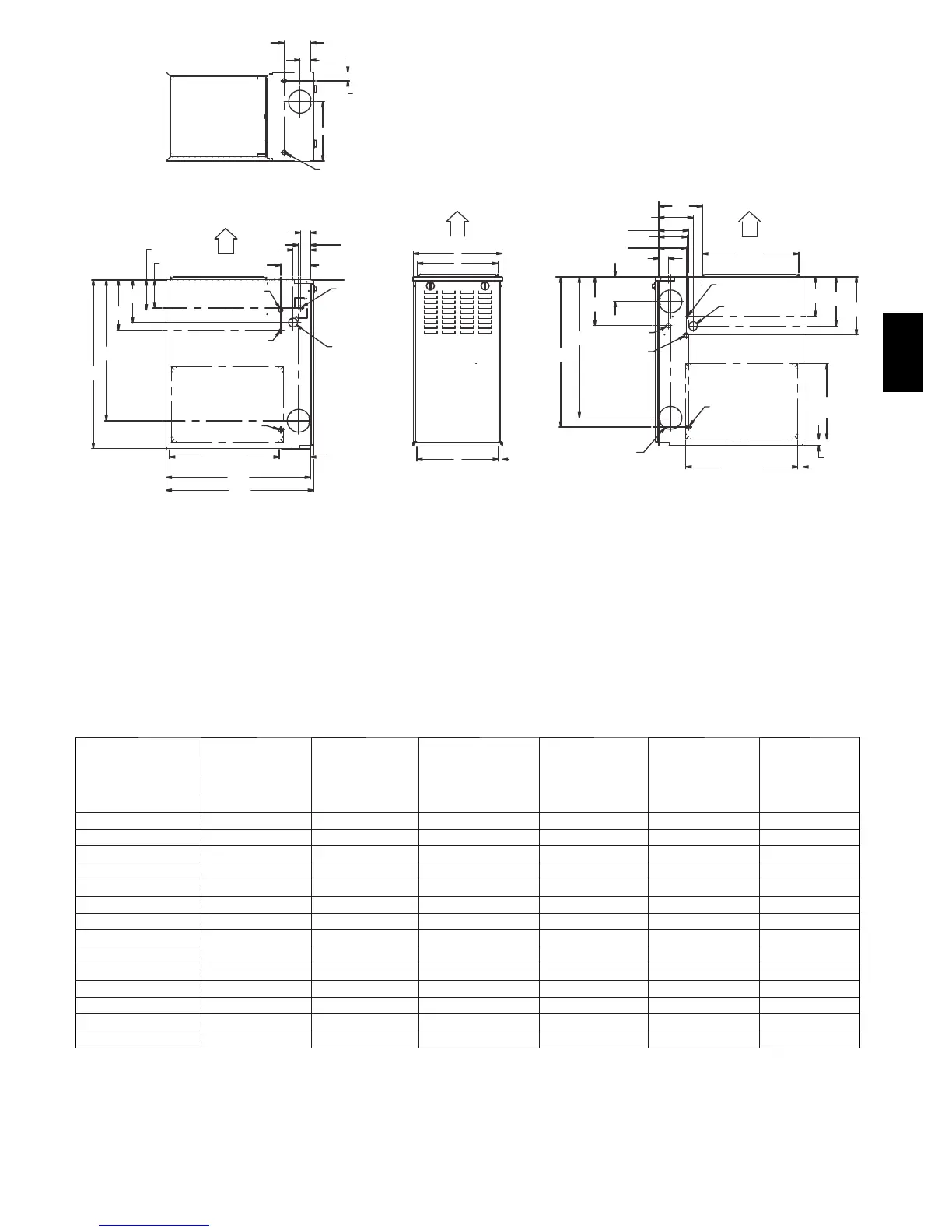
NOTES:
1. Two additional 7/8 ---in. (22 mm) diameter holes are located in the top plate.
2. Minimum return---air openings at furnace, based on metal duct. If flex duct is used, see flex duct manufacturer’s recommendations for equivalent diameters.
(a.) For 800 CFM ---16 ---in. (406 mm) round or 14 1/ 2 x 12 ---in. (368 x 305 mm) rectangle.
(b.) For 1200 CFM---20 ---in. (508 mm) round or 14 1/2 x 19 1/2---in. (368 x 495 mm) rectangle.
(c.) For 1600 CFM---22 ---in. (559 mm) round or 14 1/2 x 22 1/16---in. (368 x 560mm) rectangle.
(d.) For a irflow requiremen ts above 1800 CFM, see Air Del ivery table in Product Data literature for specific use of single side inl ets. The use of both side
inlets, a combination of 1 side a nd the bottom, or the bottom onl y will en sure adequate return air openings for airflow requirements a bove 1800 CFM.
Fig. 1 --- Dimensional Drawing
Table 1—Dimensions -- In. (mm)
FURNACE SIZE
A
CABINET
WIDTH
B
OUTLET
WIDTH
C
TOP & BOTTOM
FLUE COLLAR
LOCATION
D
BOTTOM
INLET WIDTH
VENT
CONNECTION
SIZE
SHIP WT
LB (KG)
045---08/024045 14---3/16 (360) 12---9/16 (319) 9---5/16 (237) 12---11/16 (322) 4 (102) 104 (47)
045---12/036045 14---3/16 (360) 12---9/16 (319) 9---5/16 (237) 12---11/16 (322) 4 (102) 107 (49)
070---08/024070 14---3/16 (360) 12---9/16 (319) 9---5/16 (237) 12---11/16 (322) 4 (102) 111 (50)
070---12/036070 14---3/16 (360) 12---9/16 (319) 9---5/16 (237) 12---11/16 (322) 4 (102) 115 (52)
070---16/048070 17---1/2 (445) 15---7/8 (403) 11--- 9/16 (294) 16 (406) 4 (102) 126 (57)
090---14/042090 17---1/2 (445) 15---7/8 (403) 11--- 9/16 (294) 16 (406) 4 (102) 127 (58)
090---16/048090 21 (533) 19---3/8 (492) 13--- 5/16 (338) 19---1/2 (495) 4 (102) 140 (64)
090---20/060090 21 (533) 19---3/8 (492) 13--- 5/16 (338) 19---1/2 (495) 4 (102) 146 (66)
110---12/036110 17---1/2 (445) 15---7/8 (403) 11--- 9/16 (294) 16 (406) 4 (102) 135 (61)
110---16/048110 21 (533) 19---3/8 (492) 13--- 5/16 (338) 19---1/2 (495) 4 (102) 146 (66)
110---22/066110 21 (533) 19---3/8 (492) 13--- 5/16 (338) 19---1/2 (495) 4 (102) 152 (69)
135---16/048135 21 (533) 19---3/8 (492) 13--- 5/16 (338) 19---1/2 (495) 4 (102)* 149 (68)
135---22/066135 24---1/2 (622) 22---7/8 (581) 15--- 1/16 (383) 23 (584) 4 (102)* 163 (74)
155---20/060155 24---1/2 (622) 22---7/8 (581) 15--- 1/16 (383) 23 (584) 4 (102)* 170 (77)
*135 and 155 size furnaces r e quire a 5 or 6---in. (127 or 152 mm) vent. Use a vent adapter between furnace and vent stack. See Installation Instructions for
complete installation requirements.
310AAV