NOTE: Read the entire instruction manual before starting the installation.
TABLE OF CONTENTS
SAFETY CONSIDERATIONS.....................................................................................................................................................................................3
INTRODUCTION..........................................................................................................................................................................................................3
CODES AND STANDARDS .......................................................................................................................................................................................3
ELECTROSTATIC DISCHARGE (ESD) PRECAUTION PROCEDURE ................................................................................................................6
APPLICATIONS ...........................................................................................................................................................................................................6
General......................................................................................................................................................................................................................6
Upflow Applications ...........................................................................................................................................................................................7
Condensate Trap Location (Factory-Shipped Orientation) ..........................................................................................................................7
Condensate Trap Tubing (Factory-Shipped Orientation) .............................................................................................................................7
Condensate Trap Location (Alternate Upflow Orientation).........................................................................................................................7
Condensate Trap Tubing (Alternate Upflow Orientation) ...........................................................................................................................8
Condensate Trap Field Drain Attachment ....................................................................................................................................................9
Pressure Switch Tubing.................................................................................................................................................................................9
Upper Collector Box and Inducer Housing (Unused) Drain Connections ..................................................................................................9
Condensate Trap Freeze Protection ..............................................................................................................................................................9
Downflow Applications............................................................................................................................................................................9
Condensate Trap Location.............................................................................................................................................................................9
Condensate Trap Tubing .............................................................................................................................................................................10
Condensate Trap Field Drain Attachment ..................................................................................................................................................11
Pressure Switch Tubing...............................................................................................................................................................................11
Condensate Trap Freeze Protection ............................................................................................................................................................11
Horizontal Left (Supply-Air Discharge) Applications ..........................................................................................................................11
Condensate Trap Location...........................................................................................................................................................................11
Condensate Trap Tubing .............................................................................................................................................................................11
Condensate Trap Field Drain Attachments.................................................................................................................................................12
Pressure Switch Tubing...............................................................................................................................................................................12
Condensate Trap Freeze Protection ............................................................................................................................................................12
Construct a Working Platform ....................................................................................................................................................................12
Horizontal Right (Supply-Air Discharge) Applications........................................................................................................................13
Condensate Trap Location...........................................................................................................................................................................13
Condensate Trap Tubing .............................................................................................................................................................................13
Condensate Trap Field Drain Attachment ..................................................................................................................................................14
Pressure Switch Tubing...............................................................................................................................................................................14
Condensate Trap Freeze Protection ............................................................................................................................................................15
Construct a Working Platform ....................................................................................................................................................................15
ama
CERTIFIED
®
As an ENERGY STAR
®
Partner, Bryant Heating
& Cooling Systems has
determined that this
product meets the
ENERGY STAR
®
guidlines
for energy efficiency.
REGISTERED QUALITY SYSTEM
Installation, Start-up, and Operating Instructions
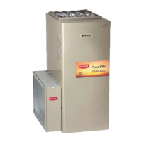
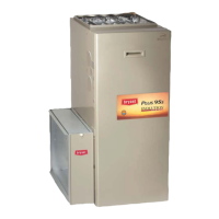
355MAV
Series F
Deluxe 4-Way Multipoise
Variable-Capacity Direct-Vent
Condensing Gas Furnace
Form: II 355M-40-11 Cancels: New Printed in U.S.A. 03-02 Catalog No. 5335-518


 Loading...