-- 3 7 --
5. Drill a 1/8-in. (3 mm) hole in 2-in. (51 mm) combustion
air pipe using the hole in intake housing as a guide.
6. Install a field-supplied No. 6 or No. 8 sheet metal screw
into combustion air pipe.
7. Install casing hole filler cap (factory-supplied in loose
parts bag) in unused combustion air pipe casing hole.
NOTE: Do not attach combustion air intake pipe permanently to
combustion air intake housings since it may be necessary to
remove pipe for service of igniter or flame sensor.
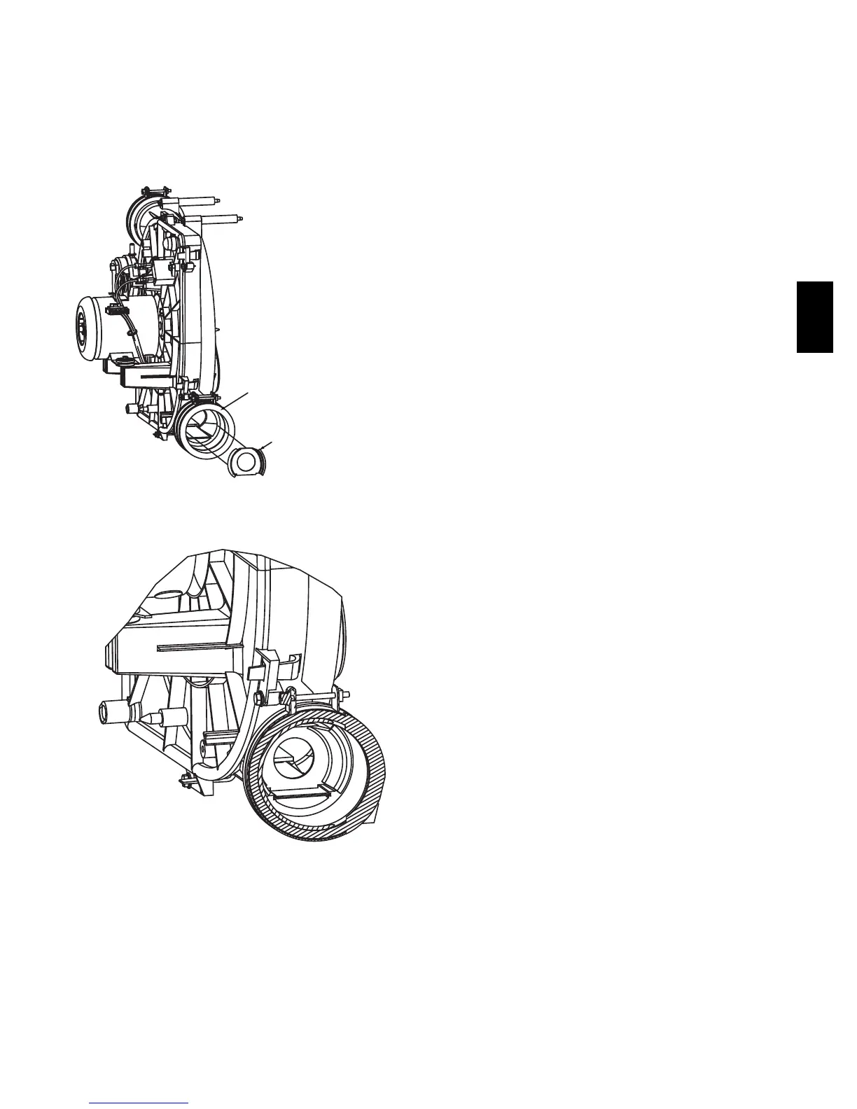
COUPLING MAY BE REMOVED
FOR EASIER INSTALLATION
INDUCER OUTLET
RESTRICTOR
A09328
Fig. 37 -- Outlet Restrictor Installation
60,000 BTUH Models only. See Table 12.
A09329
Fig. 38 -- Illustration of an Installed Outlet Restrictor
60,000 BTUH Models only. See Table 12.
340AAV