21
Table 5 – Approved Combustion--Air and Vent Pipe, Fitting and Cement Materials (U.S.A Only*)
ASTM
SPECIFICATION
(MARKED ON MATERIAL)
MATERIAL
PIPE
FITTINGS
SOLVENT CEMENT AND
PRIMERS
DESCRIPTION
D1527 ABS Pipe — — S c h e d u l e --- 4 0
D1785 PVC Pipe — — S c h e d u l e --- 4 0
D2235 For ABS — — Solvent Cement For ABS
D2241 PVC Pipe — — S D R --- 2 1 & S D R --- 2 6
D2466 PVC — Fittings — S c h e d u l e --- 4 0
D2468 ABS — Fittings — S c h e d u l e --- 4 0
D2564 For PVC — — Solvent Cement For PVC
D2661 ABS Pipe Fittings — DWV at Schedule---40 IPS sizes
D2665 PVC Pipe Fittings — DWV
F438 CPVC — Fittings — S c h e d u l e --- 4 0
F441 CPVC Pipe — — S ch e d u le --- 4 0
F442 CPVC Pipe — — SDR
F493 For CPVC — — Solvent Cement For CPVC
F628 ABS Pipe — —
Cellular Core DWV at Schedule --- 40
IPS sizes
F656 For PVC — — Primer For PVC
F891 PVC Pipe — — Cellular Core Schedule--- 40 & DWV
*Refer to Page 1 for Canadian installations.
CARBON MONOXIDE POISONING HAZARD
Failure to follow this warning could result in property
damage, personal injury, or death.
All combustion--air and vent pipes must be airtight and
watertight. Pipes must also terminate exactly as shown in Fig.
31 for direct vent (2--pipe) system or Fig. 32 for ventilated
combustion air option.
!
WARNING
An abandoned masonry chimney may be used as a raceway for
properly insulated and supported combustion--air (when
applicable) and vent pipes. Each furnace must have its own set of
combustion--air and vent pipes and be terminated individually, as
shown in Fig. 31 for Direct Vent (2--Pipe) system or Fig. 32 for
ventilated combustion air option.
A furnace shall not be connected to a chimney flue serving a
separate appliance designed to burn solid fuel.
Other gas appliances with their own venting system may also use
the abandoned chimney as a raceway providing it is permitted by
local code, the current edition of the National Fuel Gas Code and
the vent or liner manufacturer’s installation instructions. Care must
be taken to prevent the exhaust gases from one appliance from
contaminating the combustion air of other gas appliances. Do not
take combustion air from inside the chimney when using the
Ventilated Combustion Air option.
UNIT MAY NOT OPERATE
Failure to follow this caution may result in intermittent unit
operation.
When vent pipe is exposed to temperatures below freezing,
such as when it passes through an unheated space or when a
chimney is used as a raceway, pipe must be insulated as
shown in Table 7 with Armaflex--type insulation.
CAUTION
!
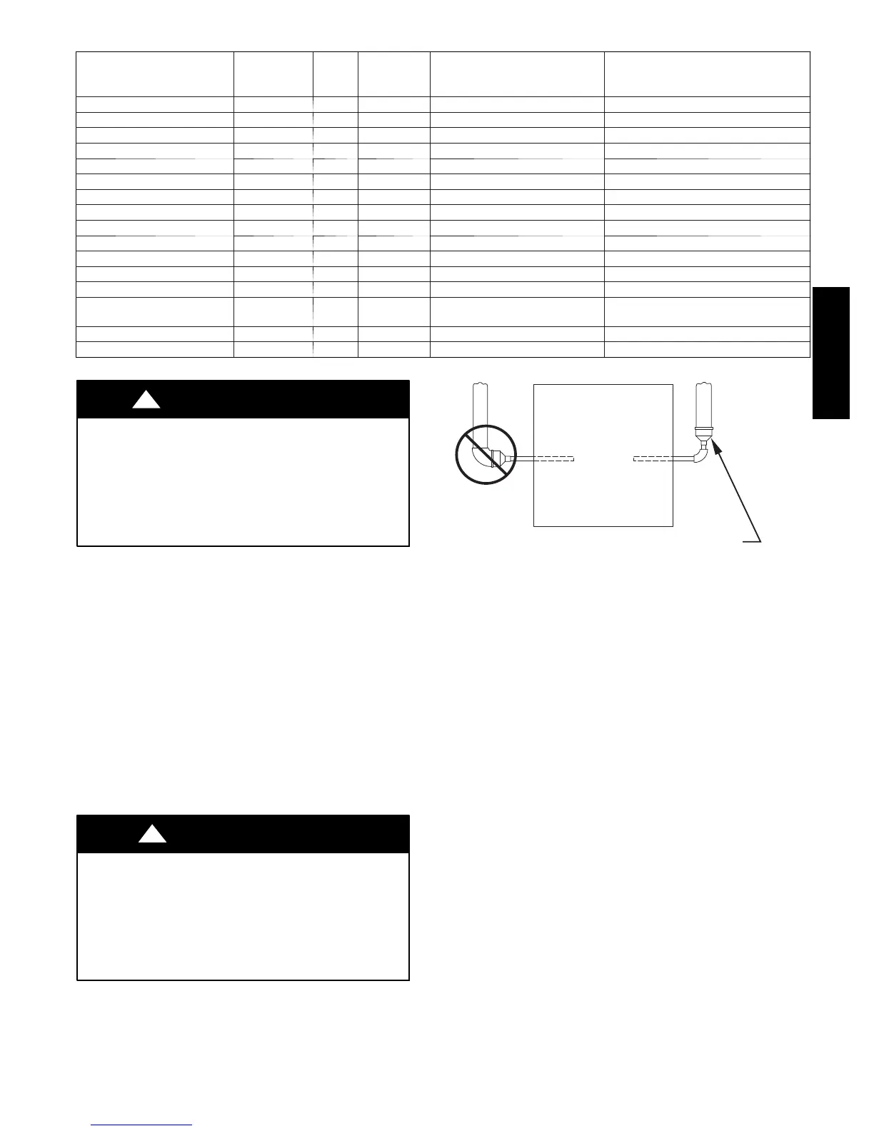
FURNACE
PIPE DIAMETER
TRANSITION IN
VERTICAL SECTION
NOT IN
HORIZONTAL
SECTION
A93034
Fig. 24 -- Combustion--Air and Vent Pipe Diameter
Transition Location and Elbow Configuration
Furnace combustion air and vent pipe connections are sized for
2--in. pipe. Any pipe size change should be made outside furnace
casing in vertical pipe. The transition has to be made as close to the
furnace as reasonably possible. (See Fig. 24.)
Installation Guidelines for Combustion Air Pipe and Vent Pipe
It is recommended that all pipes be cut, prepared, and preassembled
before permanently cementing any joint.
1. Attach combustion air pipe and vent pipe per instructions in
sections “Combustion Air Pipe” and “Vent Pipe.”
2. Working from furnace to outside, cut pipe to required
length(s).
3. Deburr inside and outside of pipe.
4. Chamfer outside edge of pipe for better distribution of
primer and cement.
5. Clean and dry all surfaces to be joined.
6. Check dry fit of pipe and mark insertion depth on pipe.
7. After pipes have been cut and preassembled, apply generous
layer of cement primer to pipe fitting socket and end of pipe
to insertion mark. Quickly apply approved cement to end of
pipe and fitting socket (over primer). Apply cement in a
light, uniform coat on inside of socket to prevent buildup of
excess cement. Apply second coat.
8. While cement is still wet, twist pipe into socket with 1/4
turn. Be sure pipe is fully inserted into fitting socket.
355BAV