26
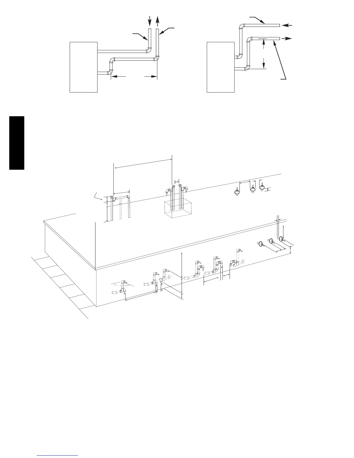
VERTICAL TO SIDEWALLVERTICAL TO ROOF
COMBUSTION-AIR PIPE
VENT PIPE
COMBUSTION-AIR PIPE
VENT PIPE
12-IN. MIN
(305 mm)
12-IN. MIN
(305 mm)
NOTE: A 12 In. (305 mm) minimum offset pipe section is
recommended with short (5 to 8 ft / 1.5 to 2.4 M) vent systems.
This recommendation is to reduce excessive condensate
A06356
Fig. 30 -- Short Vent (5 to 8 Ft. / 1.5 to 2.4 M) System
At least 36 in.
18 in. maximu m
V e r tical separation
between comb ustion
air and v ent
8 3/4 in. (222mm)f or 3 in. (76mm)ki t
6 3/4 in. (172mm)f or 2 in. (51mm) ki t
Roof T e rm ination (Pref erred)
Abandoned masonr y
used as race wa y
(per code)
At least
36 in.
A
Maintain 12
in.
min. clearance abo ve
highest anticipated
sno w le ve l, maximum of
24 in . abo v e roof
Concent ri c V ent and Comb ustion Ai r
Roof T er mination (pre fe rred)
1
in.
(25mm)
maximum (typ) from wall to inlet
12
in. (305mm)
minimum fro m
ov erhang or roof
Maintain 12
in.
min. clearance ab ov e
highest anticipated
sno w le v el or grade
which eve r is greate r
A
A
t le
a
s t
3
6
in
.
Concent ri c V ent
and Comb ustion - Air
Side T e rm inatio n
A
At least 36 in.
Side wa ll te rm inatio n
of less than 12
in. (305mm)
above highest snow level
12
in.
min fro m
ov erhang or roof
12
in.
(305mm)
separation between
bottom ofcomb ustion air and
bottom of v ent (typ)
Maintain 12
in.
min. clearance abo ve
highest anticipated
sno w le ve l or grade
whiche ve r is greater (typ)
A
A t least 36 in
.
A
Maintain 12 in. (305mm)min.
clearance abo ve
highest anticipated
sno w le ve l
Maximum of 24 in.(614mm)
abo v e roof
90 °
Note: "A" denotes 0 to < 2 in.
Between the first 2 vents
Third vent must be > 36 in. away
(typ)
(914mm)
(305mm)
(914mm)
(305mm)
(305mm)
(914mm)
(914mm)
(457mm)
(51mm)
(914mm)
A05090
Fig. 31 -- Combustion Air and Vent Pipe Termination
for Direct Vent (2--pipe) System (All Sizes)
355BAV