NOTE: Read the entire instruction manual before starting the
installation.
These procedures are for sizes 65,000 through 150,000 Btuh units.
Index Page
SAFETY CONSIDERATIONS.....................................................1
CARE AND MAINTENANCE..................................................1-5
Air Filter Arrangement..........................................................2-3
Blower Motor and Wheel......................................................3-4
Cleaning Heat Exchanger......................................................4-5
Electrical Controls and Wiring.................................................5
Pilot ...........................................................................................5
Troubleshooting ........................................................................5
Unit Wiring Diagram ............................................................6-7
Troubleshooting Chart ..............................................................8
SAFETY CONSIDERATIONS
Installing and servicing heating equipment can be hazardous due to
gas and electrical components. Only trained and qualified person-
nel should install, repair, or service heating equipment.
Untrained personnel can perform basic maintenance functions
such as cleaning and replacing air filters. All other operations must
be performed by trained service personnel. When working on
heating equipment, observe precautions in the literature, on tags,
and on labels attached to or shipped with the unit and other safety
precautions that may apply.
Follow all safety codes. In the United States, follow all safety
codes including the National Fuel Gas Code NFPA No. 54-
1992/ANSI Z223.1-1992 (NFGC). In Canada, refer to the current
edition of the National Standard of Canada CAN/CGA-B149.1-
and .2-M91 Natural Gas and Propane Gas Installation Codes
(NSCNGPIC). Wear safety glasses and work gloves. Have fire
extinguisher available during start-up and adjustment procedures
and service calls.
Recognize safety information. This is the safety-alert symbol
.
When you see this symbol on the furnace and in instructions or
manuals, be alert to the potential for personal injury.
Understand the signal word DANGER, WARNING, or CAU-
TION. These words are used with the safety-alert symbol. DAN-
GER identifies the most serious hazards which will result in severe
personal injury or death. WARNING signifies a hazard that could
result in personal injury or death. CAUTION is used to identify
unsafe practices which would result in minor personal injury or
product and property damage. NOTE is used to highlight sugges-
tions that will result in enhanced installation, reliability, or
operation.
WARNING: The ability to properly perform mainte-
nance on this equipment requires certain expertise, me-
chanical skills, tools, and equipment. If you do not
possess these, do not attempt to perform any maintenance
on this equipment other than those procedures recom-
mended in the User’s Manual. FAILURE TO FOLLOW
THIS WARNING COULD RESULT IN POSSIBLE
DAMAGE TO THIS EQUIPMENT, SERIOUS PER-
SONAL INJURY, OR DEATH.
CARE AND MAINTENANCE
For continuing high performance and to minimize possible equip-
ment failure, it is essential that periodic maintenance be performed
on this equipment. Consult your local dealer as to the proper
frequency of maintenance and the availability of a maintenance
contract.
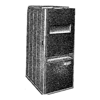
Fig. 2—Model 394HAD Upflow
A92057
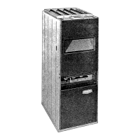
Fig. 1—Model 396HAD
Downflow
A92058
®
ama
CANADIAN GAS ASSOCIATION
A PPR O V ED
R
service and
maintenance procedures
GAS-FIRED
INDUCED-COMBUSTION FURNACES
Cancels: SP04-13 SP04-19
11-1-93
394HAD
396HAD
Series C
—1—
→