Do you have a question about the Bryant 394U and is the answer not in the manual?
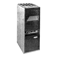
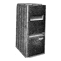
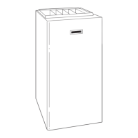
Describes the Bryant Model 394 furnace configurations: Upflow, Counter-Flow, and Basement.
Covers essential inspection points and recommendations for air filters when used with cooling.
Step-by-step instructions for cleaning burners, pilots, baffles, and combustion chambers.
Covers blower lubrication, filter cleaning/replacement, and heat exchanger inspection.
This document provides comprehensive installation and maintenance instructions for the Bryant Model 394 gas-fired forced air furnace, designed for residential heating applications. The furnace is versatile, supporting installation as an upflow, counter-flow, or basement unit, accommodating various home layouts and existing ductwork configurations. For counter-flow and basement installations, specific accessory boxes and additional instructions are available, ensuring proper integration and operation. The manual emphasizes adherence to local utility and jurisdictional requirements, referencing the American Standard "Installation of Gas Appliances and Gas Piping" (ASA Z21.30-1964) as a guiding standard for safe and effective installation practices.
The Bryant Model 394 furnace serves as a central heating appliance, utilizing natural gas or propane to generate warm air that is then distributed throughout a building via a forced air system. The core function involves a combustion chamber where gas is ignited, heating a heat exchanger. A blower then circulates air over the heated exchanger, warming it before it is pushed into the ductwork. The furnace incorporates a built-in draft diverter, simplifying venting requirements by allowing connection to a permanent chimney or a listed Type B or Type C gas vent. Control options include D4, D5, and D2 systems, which manage pilot ignition, main burner operation, and safety features. The D4 controls are typically for natural gas, while D2 and D5 controls are designed for propane gas, each featuring specific pilot and gas valve configurations. Safety is paramount, with features like a secondary limit switch to prevent overheating and automatic pilot systems that shut off gas flow if the pilot flame is not established.
The furnace offers flexible installation options, including upflow, counter-flow, and basement configurations. For upflow installations, the unit draws return air from the bottom or side and discharges heated air from the top. Counter-flow setups reverse this, drawing air from the top and discharging from the bottom, often suitable for slab or crawl space homes. Basement installations typically involve a drop duct for return air.
The unit is designed for use with summer air conditioning, with recommendations for leaving ample space for future coil box installation. Bryant manufactures specific coil boxes for upflow furnaces to facilitate air conditioning integration, which can save time and money if installed concurrently with the furnace. The manual explicitly states that the furnace is not approved for use with air conditioning units mounted upstream from the heat exchanger, emphasizing the importance of proper cooling coil placement (downstream or bypassed) to prevent chilled air from entering the furnace.
The blower system, whether direct drive or belt drive, is adjustable to optimize air delivery and temperature rise. Direct drive blowers feature multiple speed taps (High, Medium, Medium-low, Low) identified by color-coded wires (Black, Blue, Yellow, Red), allowing installers to select the appropriate speed based on voltage and desired temperature rise. Belt drive blowers, on the other hand, utilize an adjustable motor pulley. By loosening a set screw and rotating the pulley clockwise (to close) or counter-clockwise (to open), the air delivery rate can be adjusted, thereby controlling the temperature rise across the furnace. This adjustability ensures efficient operation and comfort tailored to specific installation requirements.
Proper location of the room thermostat is critical for optimal performance, with guidelines provided to avoid exposure to drafts, heat sources, or areas with restricted air circulation. The thermostat's heat anticipator setting is also specified for accurate temperature control. Gas piping installation includes recommendations for avoiding low spots, installing a drip leg to trap condensate and dirt, and positioning the main manual gas shut-off valve at an accessible height. For natural gas units, a factory-installed combination pressure regulator and main shut-off/pilot supply shut-off valve are integrated, while propane units require external pressure regulation at the supply tank.
The manual outlines several maintenance procedures to ensure the longevity and efficient operation of the furnace. Filters are a key maintenance item, requiring frequent examination for clogging. Disposable filters should be replaced when dirty, while permanent types can be cleaned with clear water and coated with water-soluble oil. This helps maintain good indoor air quality and prevents strain on the blower.
Blower motor maintenance varies by type. Direct drive blower motors are sealed units and do not require oiling. Belt drive blower motors, however, are equipped with oil cups and should be oiled at least twice a year with SAE 30 oil. Blower bearings are semi-permanently lubricated, typically lasting 3 to 5 years, and can be re-lubricated with Plastic E, available from Bryant's Service Parts Department, when necessary.
Cleaning the furnace involves a detailed process for accessing and cleaning the combustion chamber and heat exchanger. This includes disconnecting pilot tubing and electrical leads, removing the front plate from the draft diverter, and detaching burners and the pilot assembly. The pilot, often attached to a burner, can be removed together, simplifying the process. Metal angle strips holding flue baffles are removed, followed by the baffles themselves, to allow access for cleaning. A flexible-handled steel cleaning brush is recommended to loosen scale and soot, which should then be removed from the bottom of the combustion chamber. Reassembly involves reversing these steps, with a specific note on ensuring the burner's back tip fits into a designated slot in the heat exchanger for proper leveling. Periodic examination of the heat exchanger for rust and soot accumulation is advised, with cleaning performed as required to maintain efficiency and prevent potential hazards.
The manual also covers start-up and adjustment procedures, including lighting the pilot, adjusting the pilot flame for optimal impingement on the thermocouple (for D2/D5 controls) or between carry-over ports (for D4 controls), and setting the main burner gas rate. For natural gas, the manifold pressure is adjusted via a regulator screw, while for propane, the supply tank regulator is adjusted. Main burner flame adjustment involves closing the air shutter until a slight yellow tip appears, then opening it just enough to clear the yellow, ensuring a clear blue flame with a well-defined inner cone. Checking controls, including the diaphragm gas control valve and limit control, is also part of the maintenance routine, ensuring all safety and operational components function correctly. The blower speed adjustment is emphasized as a critical step before fine-tuning the fan control switch, ensuring the temperature rise across the furnace does not exceed 105 degrees F.
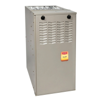
| Model | 394U |
|---|---|
| Configuration | Upflow/Horizontal |
| Heating Capacity | 40, 000 to 120, 000 BTU/h |
| Fuel Type | Natural Gas or Propane |
| Warranty (Parts) | 10 Years |
| Vent Type | Direct Vent |
| Warranty (Heat Exchanger) | Lifetime |