UNIT
549B
STANDARD
UNIT
WEIGHT
CORNER
WEIGHT
(A)
CORNER
WEIGHT
(B)
CORNER
WEIGHT
(C)
CORNER
WEIGHT
(D)
‘‘H’’ ‘‘J’’ ‘‘K’’
Lb Kg Lb Kg Lb Kg Lb Kg Lb Kg ft-in. mm ft-in. mm ft-in. mm
090 870 395 195 90 183 83 237 108 252 114 28-0
7
⁄
8
9 632 38-5
5
⁄
16
9 1050 28-9
11
⁄
16
9 856
120 1000 454 231 105 214 97 269 122 286 130 28-10
7
⁄
8
9 885 48-1
5
⁄
16
9 1253 38-0
3
⁄
8
9 924
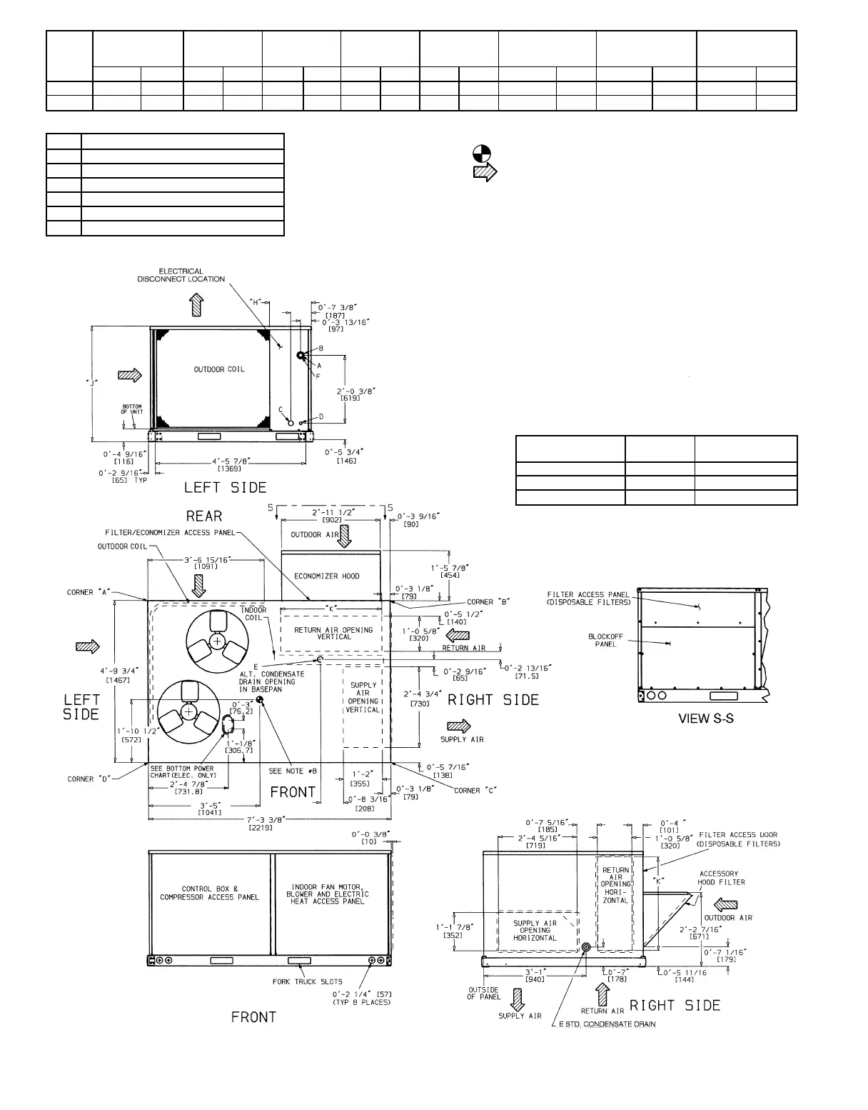
Fig. 2 — Base Unit Dimensions
NOTES:
1. Dimensions in [ ] are in millimeters.
2. Center of Gravity.
3. Direction of airflow.
4. Ductwork to be attached to accessory roof curb only.
5. Minimum clearance (local codes or jurisdiction may prevail):
a. Bottom to combustible surfaces (when not using curb) 0 in., on horizon-
tal discharge units with electric heat, 1 in. clearance to ductwork for 1 ft.
b. Outdoor coil, for proper airflow, 36 in. one side, 12 in. the other. The
side getting the greater clearance is optional.
c. Overhead, 60 in. to assure proper outdoor fan operation.
d. Between units, control box side, 42 in. per NEC (National Electrical Code).
e. Between unit and ungrounded surfaces, control box side, 36 in. per NEC.
f. Between unit and block or concrete walls and other grounded surfaces,
control box side, 42 in. per NEC.
g. Horizontal supply and return end, 0 inches.
6. With the exception of the clearance for the outdoor coil and combustible
surfaces as stated in notes 5a, b, and c, a removable fence or barricade
requires no clearance.
7. Units may be installed on combustible floors made from wood or Class A,
B, or C roof covering material.
8. The vertical center of gravity is 18-7
1
⁄
2
9 [495] for 090, 28-69 [610] for 120 up
from the bottom of the base rail.
CONNECTION SIZES
A 1
3
⁄
8
9 Dia. [35] Field Power Supply Hole
B 2
1
⁄
2
9 Dia. [64] Power Supply Knock-Out
C 1
3
⁄
4
9 Dia. [44] Charging Port Hole
D
7
⁄
8
9 Dia. [22] Field Control Wiring Hole
E
3
⁄
4
9-14 NPT Condensate Drain
F 29 Dia. [51] Power Supply Knock-Out
BOTTOM POWER CHART
These holes req’d for use with accessory packages —
CRBTMPWR001A00 (
1
⁄
2
9,
3
⁄
4
9) or CRBTMPWR002A00 (
1
⁄
2
9,1
1
⁄
4
9)
THREADED
CONDUIT SIZE
WIRE
USE
REQ’D HOLE
SIZES (MAX.)
1
⁄
2
( 24V
7
⁄
8
9 [22.2]
3
⁄
4
( Power* 1
1
⁄
8
9 [28.4]
1
1
⁄
4
( Power* 1
3
⁄
4
9 [44.4]
*Select either
3
⁄
4
9 or 1
1
⁄
4
9 for power, depending on wire size.
—2—