1
549J
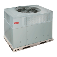
SINGLE PACKAGE ROOFTOP
HEAT PUMP
SIZES 07 -- 09 with PURON
R
(R--410A) REFRIGERANT
Installation Instructions
NOTE: Read the entire instruction manual before starting
the installation.
TABLE OF CONTENTS
SAFETY CONSIDERATIONS 2....................
Rated Indoor Airflow (cfm) 3.....................
REFRIGERATION SYSTEM COMPONENTS 8.......
INSTALLATION 10..............................
Jobsite Survey 10...............................
Step 1 -- Plan for Unit Location 10.................
Roof Mount 10..............................
Step 2 -- Plan for Sequence of Unit Installation 10.....
Curb--Mounted Installation 10..................
Pad--Mounted Installation 10...................
Frame-- Mounted Install ation 10.................
Step 3 -- Inspect Unit 10..........................
Step 4 -- Provide Unit Support 10..................
Roof Curb Mount 10.........................
Slab Mount (Horizontal Units Only) 12..........
Alternate Unit Support
(In Lieu of Curb or Slab Mount) 12.............
Step 5 -- Field Fabricate Ductwork 12...............
For Units with Accessory Electric Heaters 12.....
Step 6 -- Rig and Place Unit 12....................
Positioning on Curb 13.......................
Step 7 -- Convert to Horizontal and Connect
Ductwork 13...........................
Step 8 -- Install Outside Air Hood 14...............
Economizer and Two Po s ition Damper Hood
Pack age Removal and Setup — Factory Optio n 14..
Economizer Hood and Two-- Position Hood 14.....
Step 9 -- Install External Condensate Trap
and Line 15............................
Step 10 -- Make Electrical Connections 15...........
Field Power Supply 15........................
Units with Factory--Installed
Non--Fused Disconnect 16.....................
Units Without Factory--Installed
Non--Fused Disconnect 17.....................
All Units 17................................
Convenie nce Outlets 17.......................
Factory Option Thru--Base Connections 18.......
Units Without Thru--Base Connections 19........
All Units 19................................
Field Control Wiring 19.......................
Thermostat 19...............................
Central Terminal Board 20......................
Commercial Defrost Control 20..................
Unit Without Thru--Base Connection Kit 22.......
Heat Anticipator Settings 22...................
Electric Heaters 22............................
Single Point Boxes & Supple mentary Fuses 23....
Single Point Boxes without Fuses 23............
Low--Voltage Control Connections 23............
Variable Frequency Drive (VFD) 2--Speed
Indoor Fan Motor System (Factory--Installed) 23....
EconoMi$e r
R
X (Fact ory--Insta lled Option) 24......
Product Description 24........................
System Components 24.......................
Specifications 24..............................
W7220 Economizer Module 24.................
Electrical 24................................
Inputs 24...................................
Outputs 25.................................
Environmental 25............................
Economizer Module Wiring Details 25...........
S--Bus Sensor Wiring 25......................
CO
2
Sensor Wiring 26........................
Interface Overview 26..........................
User Interface 26............................
Keypad 26.................................
Menu Structure 27.............................
Setup and Configuration 27.....................
Time--out and Screensaver 27..................
Sequence of Operation 33.......................
Enthalpy Settings 36...........................
Two--Speed Fan Operation 36....................
Checkout 37.................................
Power Up 37................................
Initial Menu Display 37.......................






 Loading...