17
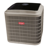
10. Secure the handle to the painted cover with (2) screws
and lock washers supplied.
11. Engaging the shaft into t he handle socket, re--install
(3) hex screws on the NFD enclosure.
12. Re--install the unit front panel.
C12279
Fig. 21 -- Handle and Shaft Assembly for NFD
Units Without Factory--Installed
Non--Fused Disconnect —
When installing units, provide a disconnect switch per
NEC (National Electrica l Code) of adequate size.
Disconnect sizing data i s provided on the unit informative
plate. L ocate on unit cabinet or within sight of the unit per
national or local codes. Do not cover unit informative
plate if mounting the disconnect on the unit cabinet.
All Units --
All field wir ing must comply w ith NEC and all local codes .
Size wire bas ed on MC A (Minimu m Circuit Amps ) on the
unit informative plate. See Fig. 18 and the unit label
diagram for power wiring connections to the unit power
terminal blocks and equipment ground. Maximum wire size
is #2 ga AWG (copper only) per pole on contactors.
Provide a ground--fault and short--circuit over--current
protection device (fuse or breaker) per NEC Article 440
(or local codes). Refer to uni t informative data plate for
MOCP (Maximum Over--current Protection) device size.
All field wiring must comply with the NEC and local
requirements.
All units except 208/230-v units are factory wired for the
voltage shown on the nameplate. If the 208/230-v unit is
to be connected to a 208-v power supply, the control
transformer must be rewired by moving the black wi re
with the
1
/
4
-in. female spade connector from the 230--v
connec tion and movi ng it to the 208-v
1
/
4
-in. male
terminal on the primary side of the transformer. Refer to
unit label diagram for additional information. Field power
wires will be connected line--side pressure lugs on the
power termi nal block or at f actory--installed option
non--fused disconnect.
NOTE: Check all factory and field electrical connections
for tightness.
Convenience Outlets —
ELECTRICAL OPERATION HAZARD
Failure to follow this warning could result in personal
injury or death.
Units with convenience outlet circuits may use
multiple disconnects. Check convenience outlet for
power status before opening unit for service. Locate
its disconnect switch, if appropriate, a nd open it.
Lock--out and tag--out this switch, if nec essary.
!
WARNING
Two types of convenience outlets are offered as
factory--installed options on 549J models: Non--powered
and unit--powered. Both types provide a 125--volt GFCI
(ground--fault circuit--interrupter) duplex receptacle rated at
15--A behind a hinged waterpr oo f access cover, located on
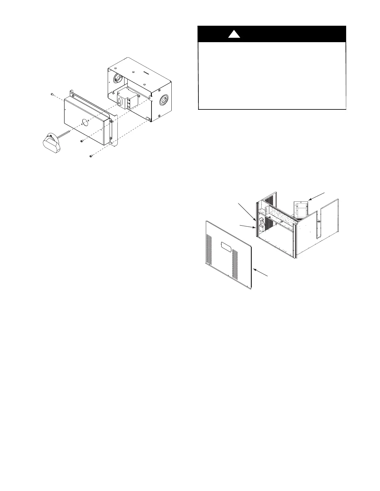
the end panel of the unit. See Fig. 22.
A 20 amp non--powered convenience outlet i s available as
a field--installed accessory.
Convenience
Outlet
GFCI
Pwd-CO
Fuse
Switch
Pwd-CO
Transformer
Control Box
Access Panel
C08128
Fig. 22 -- Convenience Outlet Location
In s t alling Weatherp r o o f Cover: A weatherproof
while-in-use cover for the factory-installed convenience
outlets is now required by UL standards. This cover cannot
be factory-mounted due its depth; it mus t be ins talled at unit
installation. For shipment, the convenience outlet is covered
with a b lank cover plate.
The weatherproof cover kit is shipped in the unit’s control
box. The kit includes the hinged cover, a backing plate
and gasket.
DISCONNECT ALL POWER TO UNIT AND
CONVENIENCE OUTLET. LOCK--OUT AND TAG--OUT
ALL POWER.
Remove the blank cover plate at the convenie nce outlet;
discard the blank cover.
Loosen the two screws at the GFCI duplex outlet, until
approximately
1
/
2
-in. (13 mm) unde r screw heads are
exposed. Press the gasket over the screw heads. Slip the
backi ng plate over the screw heads at the keyhole slots
and align with the gasket; tighten the two screws until
snug (do not over-tighten).
 Loading...