13
DETAIL “A”
PLACE ALL SEAL STRIP IN PLACE
BEFORE PLACING UNIT ON ROOF CURB.
DUCT END
SEE DETAIL “A”
“C”
“B”
“A”
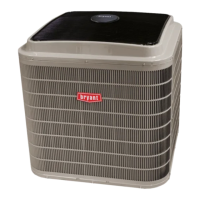
914-1371
(36"-54")
SPREADER
BARS
REQUIRED
C10410
UNIT
MAX WEIGHT
DIMENSIONS
A B C
LB KG IN. MM IN. MM IN. MM
549J*07A/D 1100 500 88.0 2235 40.8 1035 41.5 1055
549J*08D 1315 598 88.0 2235 41.6 1057 49.5 1257
549J*09D 1505 684 88.0 2235 40.0 1015 49.5 1257
NOTES:
1. Dimensions in ( ) are millimeters.
2. Hook rigging shackles through holes in base rail, as shown in detail “A.” Holes in base rails are centered
around the unit center of gravity. Use wooden top to prevent rigging straps from damaging unit.
Fig. 9 -- Rigging De tails
When using t he standard side drain connection, ensure the
red plug in the alternate bottom connection is tight. Do
this before setting the unit in place. The red drain pan
plug can be tighte ned with a
1
/
2
--in. square socket drive
extension. For further details see “Step 9 -- Install External
Condensate Trap and Line” on page 15.
Before setting the unit onto the curb, recheck gasketing on
curb.
PositioningonCurb—
Position unit on roof curb so that the following clearances
are maintained:
1
/
4
in. (6.4 mm) clearance between the
roof curb and the base rail inside the front and rear, 0.0 in.
clearance between the roof curb and the base rail inside on
the duct end of the unit. This will result in the distance
betwee n the roof curb and the base rail i nside on the
condenser end of the unit bei ng approxim ate ly
1
/
4
in.
(6.4 mm).
Although unit is weatherproof, guard against water from
higher level runoff and overhangs.
For size 08 and 09 units: after unit is in position, remove
the compressor access panel. Holding the blocking
betwee n compressors with one hand, cut the strapping.
Careful ly remove the blocking without damaging t ubing,
wiring, or controls. Remove the strapping and re place the
access panel.
Remove al l shipping materials and top skid. Recycle or
dispose of all shipping materials.
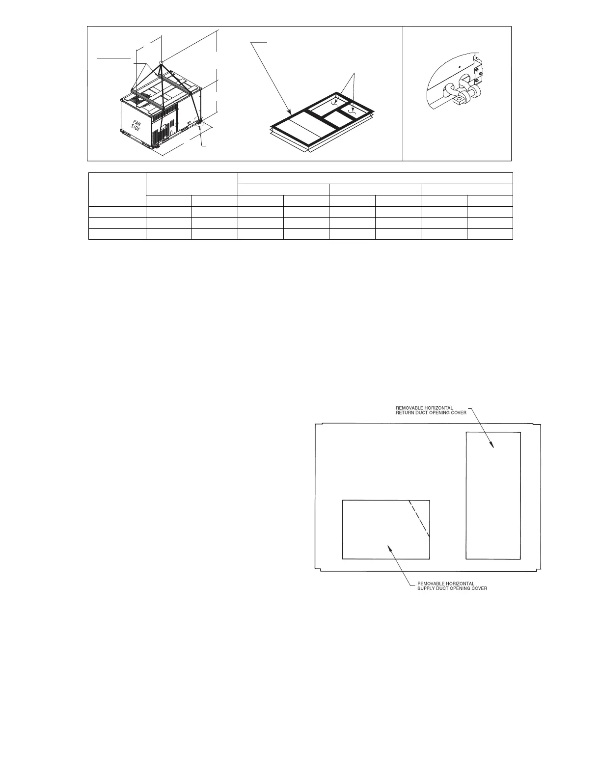
Step 7 — Convert to Horizontal and Connect
Ductwork (when required)
Unit is shipped in the vertical duct configuration. Unit
without factory--installed economizer or return air smoke
detector option may be field--converted to horizontal ducted
configuration. T o convert to horizontal configuration,
remove screws from side duct opening covers and remove
covers. Using the same screws , ins tall covers on vertical
duct openings with the insulation--side down. Seals around
duct openings must be tight. See Fig. 10.
C06108
Fig. 10 -- Horizontal Conversion Panels
Field--supplied flanges should be attached to horizontal
duct openings and all ductwork should be secured to the
flanges. Insulate and weatherproof all external ductwork,
joints, and roof or building openings with counter flashing
and mastic in accordance with applicable codes.
Do not cover or obscure visibility to the unit’s informative
data plate when insulating horizontal ductwork.
 Loading...