18
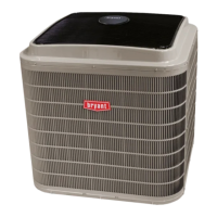
Mount the weatherproof cover to the backing plate as
shown in Fig. 23. Remove two slot fillers in the bottom of
the cover to permit service tool cords to exit the cover.
Check for full closing and latching.
RECEPTACLE
NOT INCLUDED
COVER – WHILE-IN-USE
WEATHERPROOF
BASE PLATE FOR
GFCI RECEPTACLE
C09022
Fig. 23 -- Weatherproof Cover Installation
Non--powered type: This type requires the field
installation of a general--purpose 125--volt 15--A circui t
powered from a source elsewhere in the building. Observe
national and local codes when sele cting wire size, fuse or
breake r requirements a nd disconnect switch size and
loca tion. Route 125--v power supply conductors into the
bottom of the utility box containing the duplex receptacle.
Unit--powered type: A unit--mounted transformer is
fact ory--installed to stepdown the main power supply
voltage to the unit to 115--v at the duplex receptacle. This
option also includes a manual switch with fuse , located in
a utility box and mounted on a bracket behind the
convenience outlet; access is through the unit’s control
box access panel. See Fig. 22.
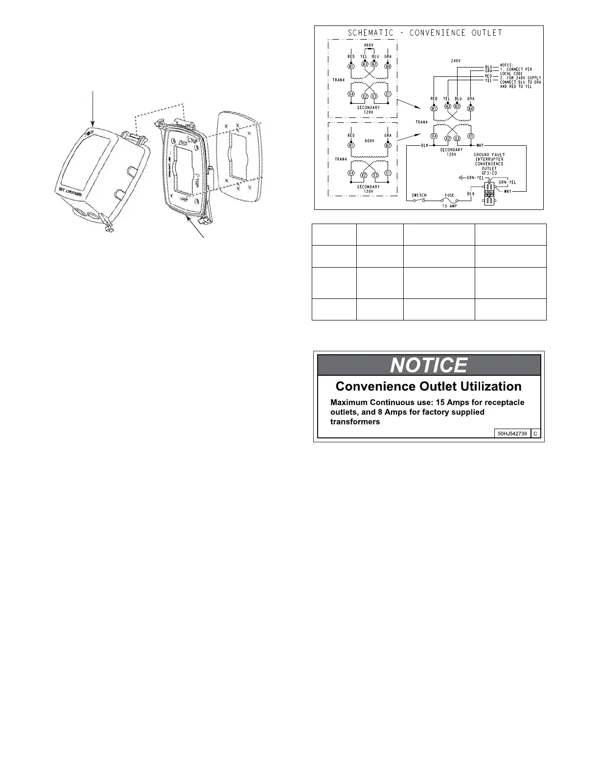
The primary leads to the convenience outlet transformer are
not factory--connected . Selection of primary power s ou rce is
a customer--option. If local codes permit, the transf or mer
primary leads can be connected at the line--side termin als on
the unit--mounted non--fused disconnect or HACR breaker
switch; this will provide service power to the unit when the
unit disconnect switch or HACR switch is open. Other
connection methods will result in the convenience outlet
circuit being de--ener gized when the unit disconn ect or
HACR switch is open. See F ig. 24.
Using unit--mounted convenience outlets: Units with
unit--mounde d convenience outlet circuits will often
require t hat two disconnects be opened to de--energize all
power to the unit. Treat all units as electrically energized
until the convenience outlet power is also checked and
de--energization is confirmed. Observe National Electrical
Code Article 210, Branch Circuits, for use of convenience
outlets.
C08283
UNIT
VOLTAGE
CONNECT
AS
PRIMARY
CONNECTIONS
TRANSFORMER
TERMINALS
208,
230
240
L1: RED +YEL
L2: BLU + GRA
H1 + H3
H2 + H4
460 480
L1: RED
Splice BLU + YEL
L2: GRA
H1
H2 + H3
H4
575 600
L1: RED
L2: GRA
H1
H2
Fig. 24 -- Powered Convenience Outlet Wiring
a549J--- 006
Fig. 25 -- Convenience Outlet Utilization Notice Label
Test the GFCI receptacle by pressing the TEST button on
the face of the receptacle to trip and open the receptacle.
Check for proper grounding wires and power line phasing
if the GFCI receptacle does not trip as required. Press the
RESET button to clear the tripped condition.
Factory Option Thru--Base Connections —
This service connection kit consists of a
1
/
2
--in. electrical
bulkhea d connector and a
3
/
4
--in. electrical bulkhead
connec tor, al l factory--installed in the embossed (raised)
section of the unit basepan in the condenser section. The
1
/
2
--in. bulkhead connector enables the low--voltage
control wires to pass through the basepan. The
3
/
4
-- i n .
electrical bulkhead connector allows the high--voltage
power wires to pass through the basepan. See Fig. 26.
 Loading...