19
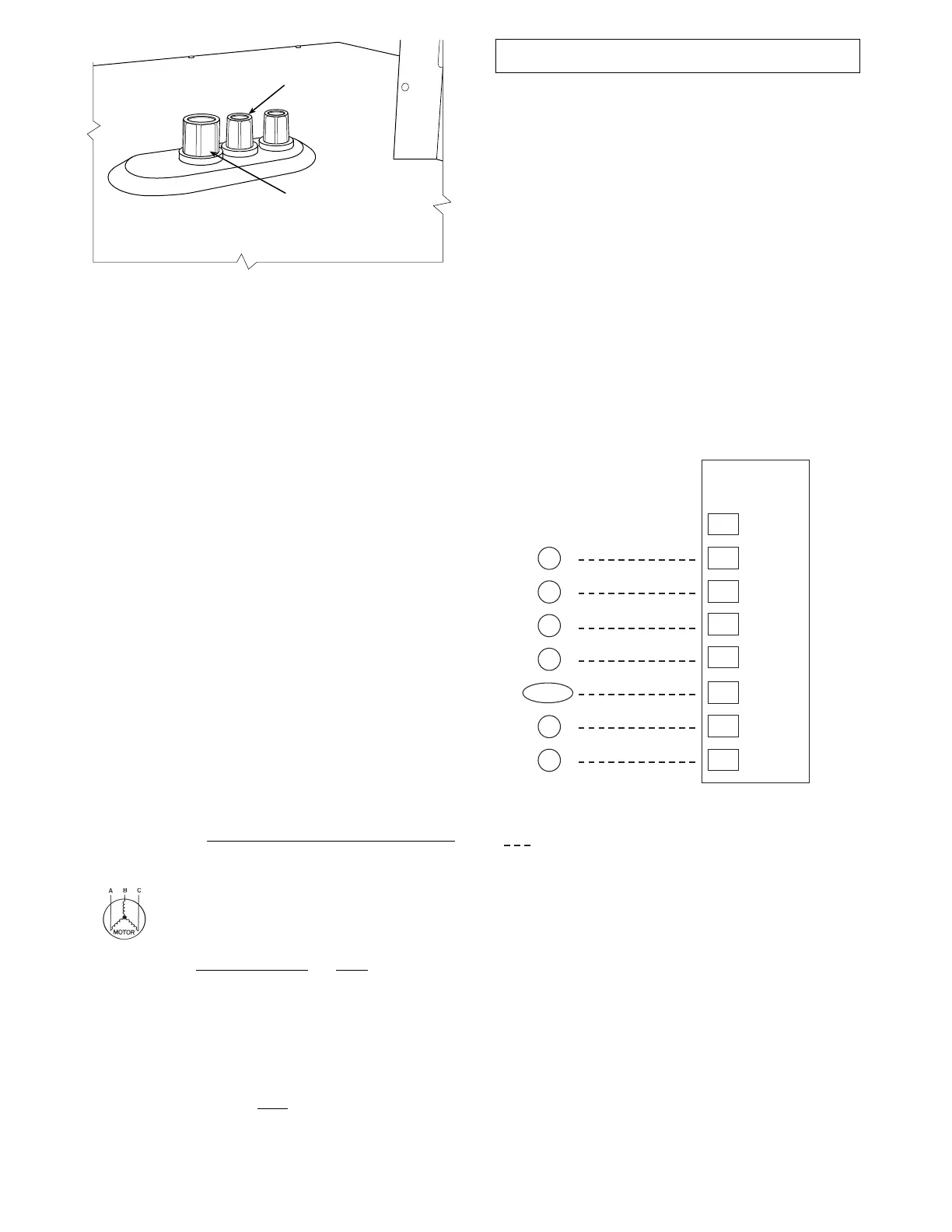
LOW VOLTAGE
CONDUIT
CONNECTOR
HIGH VOLTAGE
CONDUIT
CONNECTOR
C13412
Fig. 26 -- Thru--Base Connection Fittings
Check tightness of connector lock nuts before connecting
electrical c onduits.
Field--supplied and field--installed liquid tight conduit
connec tors and conduit may be attached t o the connectors
on the basepan. Pull correctly rated high voltage and low
voltage through appropriat e condui ts. Connect the power
conduit to the internal disconnect (if unit is so equipped)
or t o the external disconnect (through unit side panel). A
hole must be field cut in the main control box bottom on
the left side so the 24--v control connections can be made.
Connect the control power conduit to the unit control box
at this hole.
Units without Thru--Base Connections —
1. Install power wiring conduit through side panel open-
ings. Install conduit between disconnect and control
box.
2. Install power li nes to terminal connections as shown
in Fig. 18.
All Units —
Voltage to compressor terminals during operation must be
within voltage range indicated on unit na meplate. On
3--phase units, voltages between phases must be balanced
within 2% and the current within 10%. Use the formula
below to determine the percent of voltage imbalance.
%Voltage
Imbalance
= 100 x
max voltage deviation from average voltage
average voltage
Example: Supply voltage is 230-3-60
AB = 224 v
BC = 231 v
AC = 226 v
Average Voltage =
(224 + 231 + 226)
=
681
= 227
3
3
Determine maximum deviation from average voltage.
(AB) 227 – 224 = 3 v
(BC) 231 – 227 = 4 v
(AC) 227 – 226 = 1 v
Maximum deviation is 4 v.
Determine percent of voltage imbalance.
%VoltageImbalance
= 100 x
4
= 1.76%
227
This amoun t of phase imbalance is satisfactory as it is below the
maximum allowable 2%.
IMPORTANT: If th e supply voltage phase imbalance is more than
2%, contact your local electric utility company immediately.
Operati on on improper line voltage or excessive phase
imbalance constitutes abuse and may cause damage to
electrical components. Such operation would invalidate
any applicable Bryant warrant y.
Field Control Wiring —
The 549J unit requires an external temperature c ontrol
devic e. This device can be a thermostat emulation device
provided as part of a third--party Building Management
System or the RTU Open controller (RTU Open controller
is available as a factory--installed option only).
Thermostat —
Select a Bryant--appr ov ed acces s or y thermostat. When
electric heat is installed in the 549J unit, the thermostat mus t
be capable of energizing the G terminal (to energ ize the
Indoor Fan Contactor) whenever there is a space call for
heat (energizing the W1 terminal). Access o ry thermostats
listed on the unit price pages can provide this signal but they
are not configured to enable this signal as shipped.
X
C
G
W2
C
W2
G
W1
O/B/Y2
Y2
R
W1
R
Y1
Y1
T
H
E
R
M
O
S
T
A
T
(Note 1)
(Note 2)
Note 1: Typical multi-function marking. Follow manufacturer’s configuration
instructions to select Y2. Do not configure for O output.
Note 2: W2 connection not required on units without electric heating.
Field Wiring
Central
Terminal
Board
Typical
Thermostat
Connections
C09012
Fig. 27 -- Typical Low--Voltage Control Connections
Install the accessory thermostat according to installation
instructions included with the accessory.
Locate the thermostat accessory on a solid wall in the
conditioned space to sense average temperature in
accordance with the thermostat installation instructions.
If the thermostat contains a logic circuit requiring 24--v
power, use a thermostat cable or equivalent single leads of
different colors with minimum of seven leads. If the
thermostat does not require a 24--v source (no “C”
connec tion required), use a thermostat cable or equivalent
with minimum of six leads. Check the thermostat
installation instructions for additional features which
might require additional conductors in the cable.
 Loading...