37
TEMPERATURE
ENTH
ALPY
RA TEMP
ABSOLUTE HUMIDITY
ECONOMIZING
AVAILABLE
NOT AVAILABLE
ES5 ES4 ES3 ES2 ES1 HL
DUAL ENTHALPY
HIGH LIMIT
SINGLE ENTHALPY
P2 (T,RH)
P1
(T,RH)
R
A
H
U
M
(
%
R
H
)
a50--- 9997
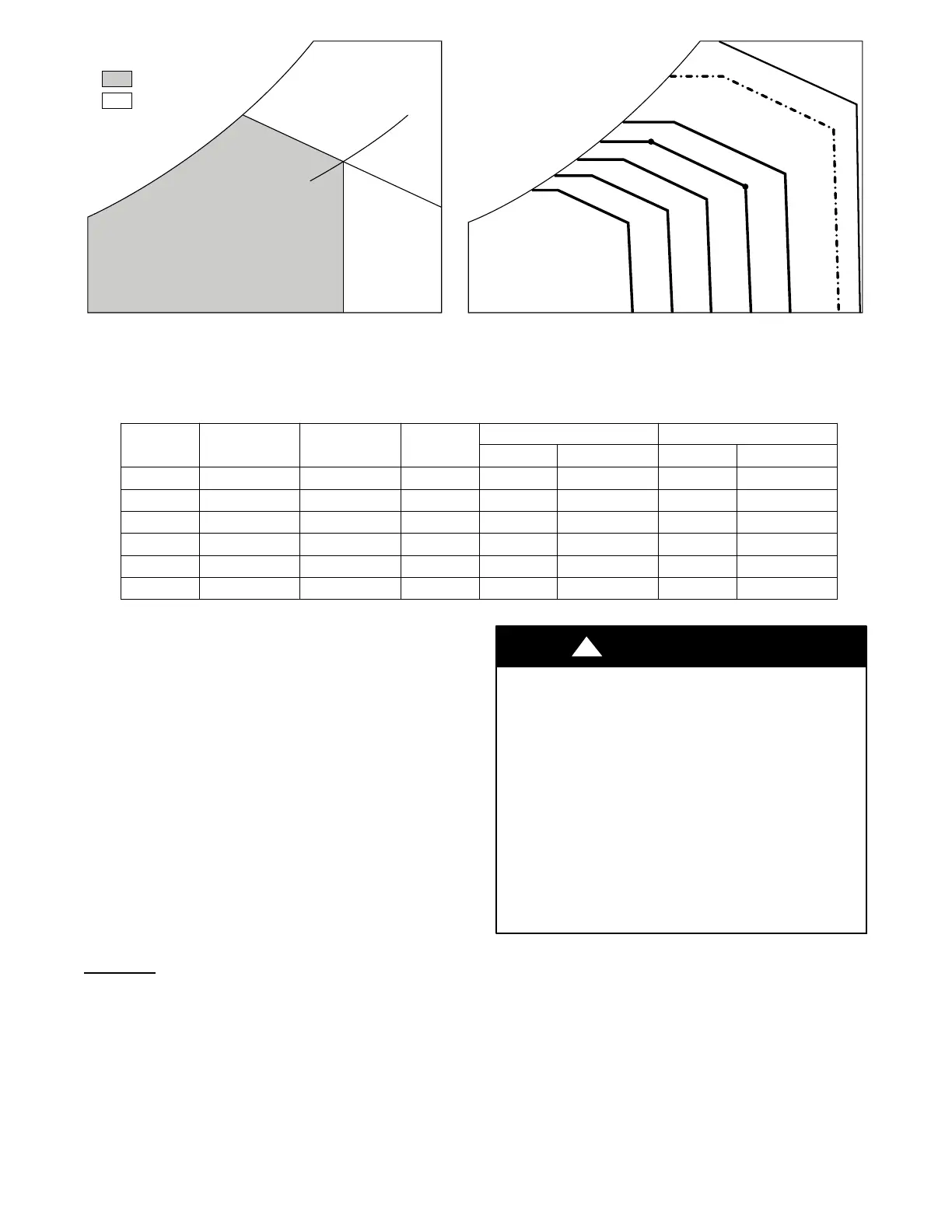
Fig. 42 -- Single Enthalpy Curve and Boundaries
Table 22 – Single Enthalpy and Dual Enthalpy High Limit Curves (EN Units)
Enthalpy
Curve
Tem p.
D r y --- B u l b ( _F)
Tem p.
Dewpoint (_F)
Enthalpy
(btu/lb/da)
Point P1 Point P2
Tem p. (_F) Humidity %RH Tem p. (_F) Humidity %RH
ES1 80.0 60.0 28.0 80.0 36.8 66.3 80.1
ES2 75.0 57.0 26.0 75.0 39.6 63.3 80.0
ES3 70.0 54.0 24.0 70.0 42.3 59.7 81.4
ES4 65.0 51.0 22.0 65.0 44.8 55.7 84.2
ES5 60.0 48.0 20.0 60.0 46.9 51.3 88.5
HL 86.0 66.0 32.4 86.0 38.9 72.4 80.3
The 2 speed fan delay is available when the system is
programmed for 2 speed fan (in the System Setup menu
item). The 2 speed fan delay is defaulted to 5 minutes and
can be changed in the Advanced Setup menu item. When
the unit has a call for Y1 In and in the free cooling mode
and there is a call for Y2 In, the 2--speed fan delay starts
and the OA damper will modulate 100% open, the supply
fan should be set to high speed by the unit controller.
After the del ay one of two act ions will happen:
S The Y2 In call will be satisfied with the damper 100%
open and fan on high speed and the call will turn off
OR
S If the ca ll for additional cooling in the space has not
been satisfied then the first stage of mechanical cooling
will be enabled through Y1 Out or Y2 Out.
Checkout
Inspect all wiri ng connections at the economizer module’s
terminals, and verify compliance with the installation
wiring diagrams.
For checkout, review t he Status of each configured
parameter and perform the Checkout tests.
NOTE: See “Interface Overview” on page 26 for
information about menu naviga tion and use of the keypad.
ELECTRICAL SHOCK HAZARD
Failure to follow this warning could cause personal
injury, death or property damage.
Before performing service or maintenance operations
on unit, always turn off main power switch to unit and
install lock(s) and lockout tag(s). Unit may have more
than one power switch. Ensure electrical service to
rooftop unit agrees with voltage an amperage listed on
the unit rating plate.
If any wiring changes are required, first be sure to
remove power from the economizer module before
starting work. Pay particular attention to verifying the
power connection (24 Vac).
!
WARNING
Power Up —
After the W7220 module is mounted and wired, apply
power.
Initial Menu Display —
On initial start up, Honeywell displays on the first line
and Economizer W7220 on the second line. After a brief
pause, the revision of the software a ppears on the first line
and the second line wil l be blank.
 Loading...