27
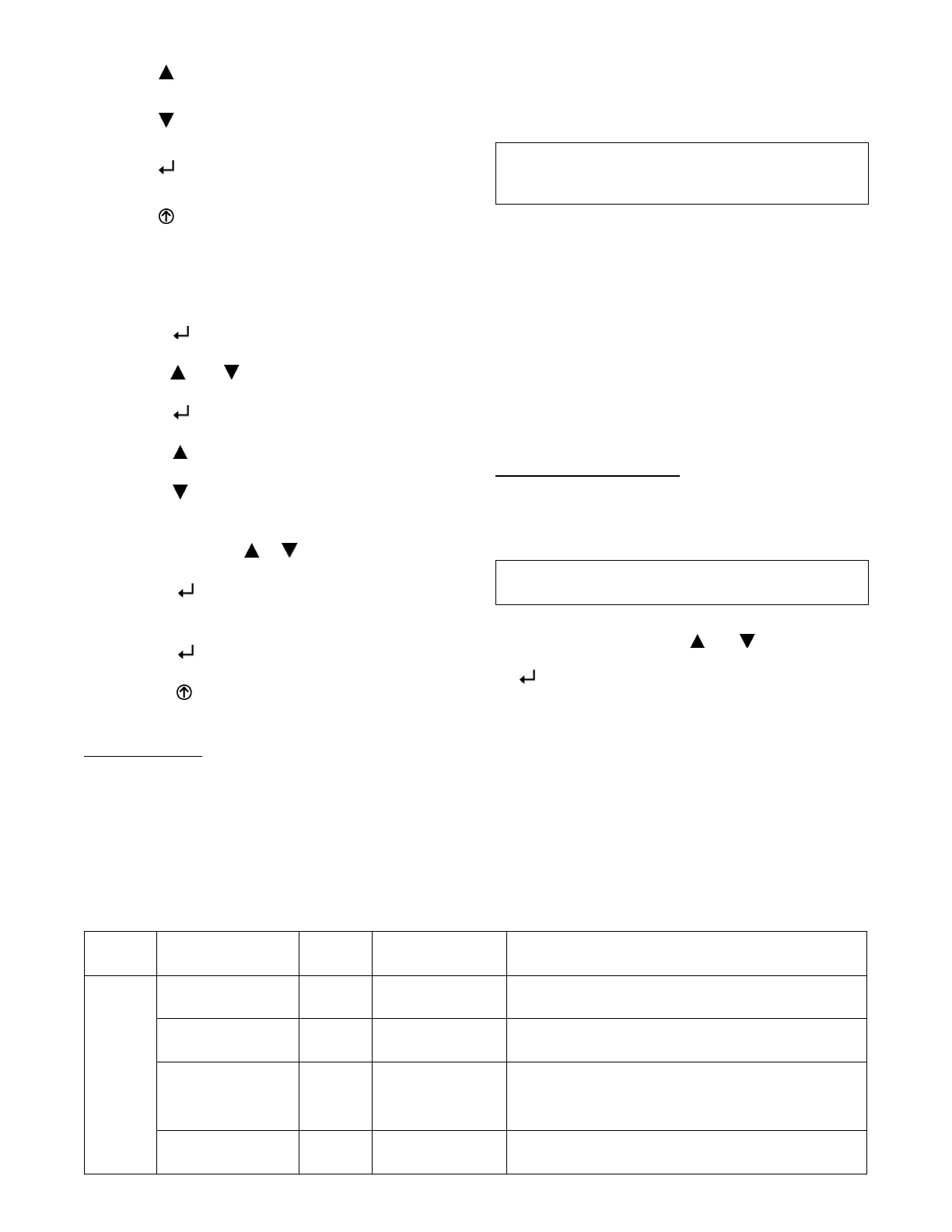
To use the keypad when working with menus:
S Press the
(Up arrow) button to move to the previous
menu.
S Press the
(Down arrow) but ton to move to the next
menu.
S Press the
(Enter) button to display the first item in
the currently displayed menu.
S Press the
(Menu Up/Exit) button to exit a menu’s
item and return to the list of menus.
To use the keypad when working with Setpoints, System
an d Adv a n ced Sett in gs, C h eck o u t tests and Ala rms :
1. Navigate to the desired menu.
2. Press the
(Enter) button to display the first item in
the currently displayed menu.
3. Use the
and buttons to scroll to the desired
parameter.
4. Press the
(Enter) button to display the value of the
currently displayed item.
5. Press the
button to increase (change) the displayed
parameter value.
6. Press the
button to decrease (change) the displayed
parameter value.
NOTE: When values a re displayed, pressing and
holding the
or button causes the
display to automatically increment.
7. Press the
(Enter) button to accept the displayed
value and store i t in nonvolatile RAM.
8. “CHANGE STORED” displays.
9. Press the
(Enter) button to return to the current
menu parameter.
10. Press the
(MenuUp/Exit)buttontoreturntothe
previous menu.
Menu Structur e
Table 12 illustrates the complete hierarchy of menus and
parameters for the EconoMi$er
R
X system.
The Menus in display order are:
S STATUS
S SETPOINTS
S SYSTEM SETUP
S ADVANCED SETUP
S CHECKOUT
S ALARMS
IMPORTANT: Table 12 illustrates the complete
hierar chy. Your menu param eters may be different
dependi ng on your configuration.
For example if you do not have a DCV (CO
2
) sensor, then
none of the DCV parameters appear and only MIN POS
will display. If you ha ve a CO
2
sensor, the DCV MIN and
DCV MAX will appear AND if you have 2 speed fan
DCVMIN(highandlowspeed)andDCVMAX(high
and low speed will appear).
NOTE: Some parameters in the menus use the letters MA
or MAT, indicating a mixed air temperature sensor
location before the cooling coil. This unit application has
the control sensor located after the cooling coil, in the fan
section, where it is designated as (Cool ing) Supply Air
Temperature or SAT sensor.
Setup and Configuration
Before being placed into service, the W7220 economizer
module must be setup and configured for the installed
system.
IMPORTANT: During setup, the economizer module is
live at all times.
The setup process uses a hierarchical menu structure that
is easy t o use. You press the
and arrow buttons to
move forward and backward through the menus and press
the
button to selec t and confirm setup item changes.
Time--out and Screensaver —
When no buttons have bee n pressed for 10 minutes, the
LCD displays a screen saver, which cycles through the
Status items. Each Status items displays in turn and cycles
to the next item after 5 seconds.
Table 12 – Menu Structure*
Menu Parameter
Parameter
Default
Value
Parameter
Range and Increment
[
EXPANDED P ARAMETER NAME
Notes
STA TUS
ECON AVAIL NO YES/NO ECONOMIZING A VAILABLE
YES = economizing available; the system can use outside air for free
coo ling when req ui re d
ECONOMIZING NO YES/NO ECONOMIZING ACTIVE
YES = Outside air being used for first stage cooling.
NO = Econom izing not active
OCCUPIED NO YES/NO OCCUPIED
YES = OCC signal recei ved from space thermostat
or unitary controlle r.
YES = 24 Vac on terminal OCC.
NO = 0 Vac on terminal OCC.
HEAT PUMP n/a** COOL
HEAT
HEAT PUMP MODE
Displays COOL or HEA T when system is set to heat pump
(non ---conventional)
 Loading...