47
Table 24 – LEDs
The LEDs on the RTU Open Controller show the status of certain functions
If this LED is on... Status is...
Power The RTU Open controller has power
Rx The RTU Open controller is receiving data from the network segment
Tx The RTU Open controller is transmitting data over the network segment
BO# The binary output is active
The Run and Error LEDs indicate control module and network status
If Run LED shows... And Erro r LED shows... Status is...
2 flashes per second Off Normal
2 flashes per second 2 flashes, alternating with Run LED Five minute auto---restart delay after system error
2 flashes per second 3flashes,thenoff Control module has just been fo rmatted
2 flashes per second 4 flashes, then pause Two or more devices on this network have the
same MSTP network address
2 flashes per second On Exec halted after frequent system errors or
control programs halted
5 flashes per second On Exec start---up aborted, Boot is running
5 flashes per second Off Firmware transfer in progress, Boot is running
7 flashes per second 7 flashes per second, alternating
with Run LED
Ten second recovery period after brownout
14 flashes per second 14 flashes per second,
alternating with Run LED
Brownout
On On Failure. Try the following solutions:
S Turn the RTU Open controller off, then on.
S Format the RTU Open controller.
S Download memory to the RTU Open controller.
S Replace the RTU Open controller.
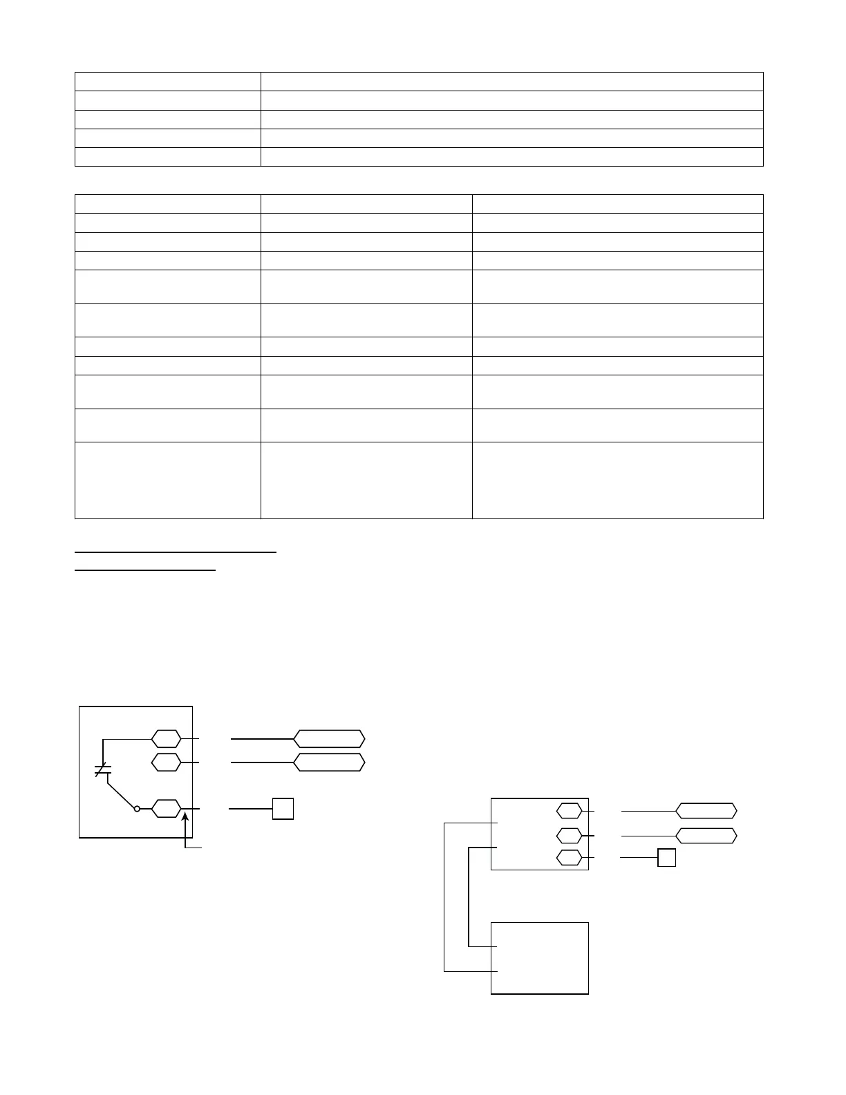
Outdoor Air Enthalpy Control
(P/N
33CSENTHSW)
The enthalpy control (33CSENTHSW) is a vailable as a
field--installed accessory to be used with the EconoMi$er2
dampe r system. The outdoor air enthalpy sensor is part of
the enthalpy control. (The separate field--installed
accessory return air enthalpy sensor (33CSENTSEN) is
required for differential enthalpy control. See Fig. 59.)
7
CTB ECON
(RTU Open: to J2-6)
LOW
GND
24V
Enthalpy
Switch
GRA
BLK
RED
Factory Wiring Harness
PL6-1 (24-V)
PL6-4 (COM)
C11169
Fig. 59 -- Enthalpy Switch (33CSENTHSW) Connections
Loca te the enthalpy control in t he economizer next to the
Actuator Motor. Locate two GRA leads in the factory
harness and connect the gray lead labeled “ESL” to the
terminal labeled “LOW”. See Fig. 59. Connect the
entha lpy cont rol powe r input terminals to economizer
act uator power leads RED (connect to 24V) and BLK
(connect to GND).
The outdoor enthalpy changeover setpoint is set at the
enthalpy controller.
Differential Enthalpy Contr ol —
Differential enthalpy control is provided by sensing and
comparing the outside air and return air enthalpy
conditions. Install the outdoor ai r e nthalpy control as
described above. Add and install a return air entha lpy
sensor.
Return Air Enthalpy Sensor —
Mount the return--air enthalpy sensor (33CSENTSEN) in
the return-- air section of the economizer. The return air
sensor is wired to the enthalpy controller
(33CSENTHSW). See Fig. 60.
GRA
BLK
RED
– 4-20
Main
+ VDC
Out
– 4-20 Main
Out
+ 24-36
VDC In
LOW
GND
24V
7
CTB ECON
(RTU Open: to J2-6)
PL6-1 (24-V)
PL6-4 (COM)
Outside Air
Enthalpy Switch
Return Air
Enthalpy
Sensor
C11170
Fig. 60 -- Outside and Return Air Enthalpy Sensor
Wiring
 Loading...