48
Smoke Detectors
Smoke detectors are available as factory--installed options on
549J models . Smoke detectors may be specified for Supply
Air only or for Return Air without or with economizer or in
combination of Supply Air and Return Air . All components
neces sary for operation are factory--provided and mounted.
The unit is factory--config ur ed for immediate smok e detector
shutdown operation; additional wiring or modifications to
unit terminal board may be neces s ary to complete the unit
and smoke detector configuration to meet project
requirements.
Units equipped with factory--optional Return Air smoke
detectors require a relocation of the sensor module at unit
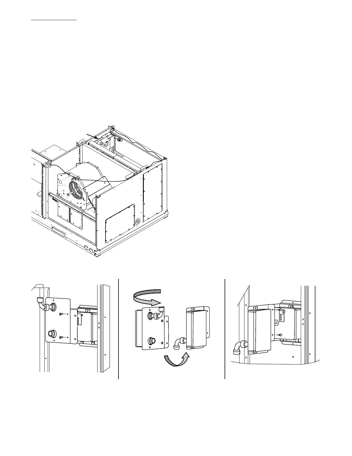
installation. See Fig. 61 for the as shipped location.
Return Air
Smoke Detector
(as shipped)
C12282
Fig. 61 -- Return Air Smoke Detector, Shipping Position
Completing Installation of Return Air Smoke Sensor:
1. Unscrew the two screws holding the Return Air
Smoke Detector assembly. See Fig. 62, Step 1. Save
the screws.
2. Turn the assembly 90 degrees and then rotate end to
end. Make sure that the elbow fitting is pointing
down. See Fig. 62, Step 2.
3. Screw the sensor and detector plate into its operating
pos itio n using screw s from Step 1. See Fig. 62, S tep 3.
4. Connect the flexible tube on the sampling inlet to the
sampling tube on the basepan.
Additional Application Data —
Refer to the Application Data sheet titled Factory
Installed Smoke Detectors For Small And Medium
Rooftop Units 2 to 25 Tons for discussions on additional
control fe atures of these smoke detectors including
multiple unit coordination.
Step 11 — Adjust Factory--Installed Options
Smoke Detectors: Smoke detector(s) will be connected at
the Controls Connections Board, at terminals marked
“Smoke Shutdown”. Remove jumper JMP 3 when ready
to energize unit.
EconoMi$e r
R
IV Occupancy Switch: Refer to Fig. 63
for general EconoMi$er IV wiring. External occupancy
control is manage d through a connect ion on the Central
Terminal Board.
If external occupancy control is desired, connect a time
clock or remotely controlled switch (closed for Occupied,
open for Unoccupied sequence) at terminals marked
OCCUPANCY on CTB. Remove or cut jumper JMP 2 to
complete the installation.
Step 1 Step 2 Step 3
C12283
Fig. 62 -- Completing Installation of Return Air Smoke Sensor
 Loading...