20
For wire runs up to 50 ft. (15 m), use no. 18 AWG
(American Wire Gage) insulated wire [35_C(95_F)
minimum]. For 50 to 75 ft. (15 to 23 m), use no. 16 AWG
insulated wire [35_C(95_F) minimum]. For over 75 ft.
(23 m), use no. 14 AWG insulated wire [35_C(95_F)
minimum]. All wire sizes larger than no. 18 AWG cannot
be directly connected to the thermostat and will require a
junction box and splice at the thermostat.
Central Terminal Board
The Central Terminal Board (CTB) is a pass through
connectio n point. The CTB pro vid es the capability to add
factory--installed options and field--installed access o ries to
the units by cutting jumper wires without having to change
or reroute wires through the structure of the unit. The CTB
does not provide any microprocessor control; it is simply a
basic multifunctio n wiring terminal configu ratio n.
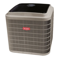
Commercial Defrost Control
The Commercial Defrost Control Board (DFB)
coordinates thermostat demands for supply fan control, 1
or 2 stage cooling, 2 stage heating, emergency heating and
defrost control with unit operating sequences. The DFB
also provides an indoor fan off de lay feature (user
selectable). See Fig. 28 for board arrangement.
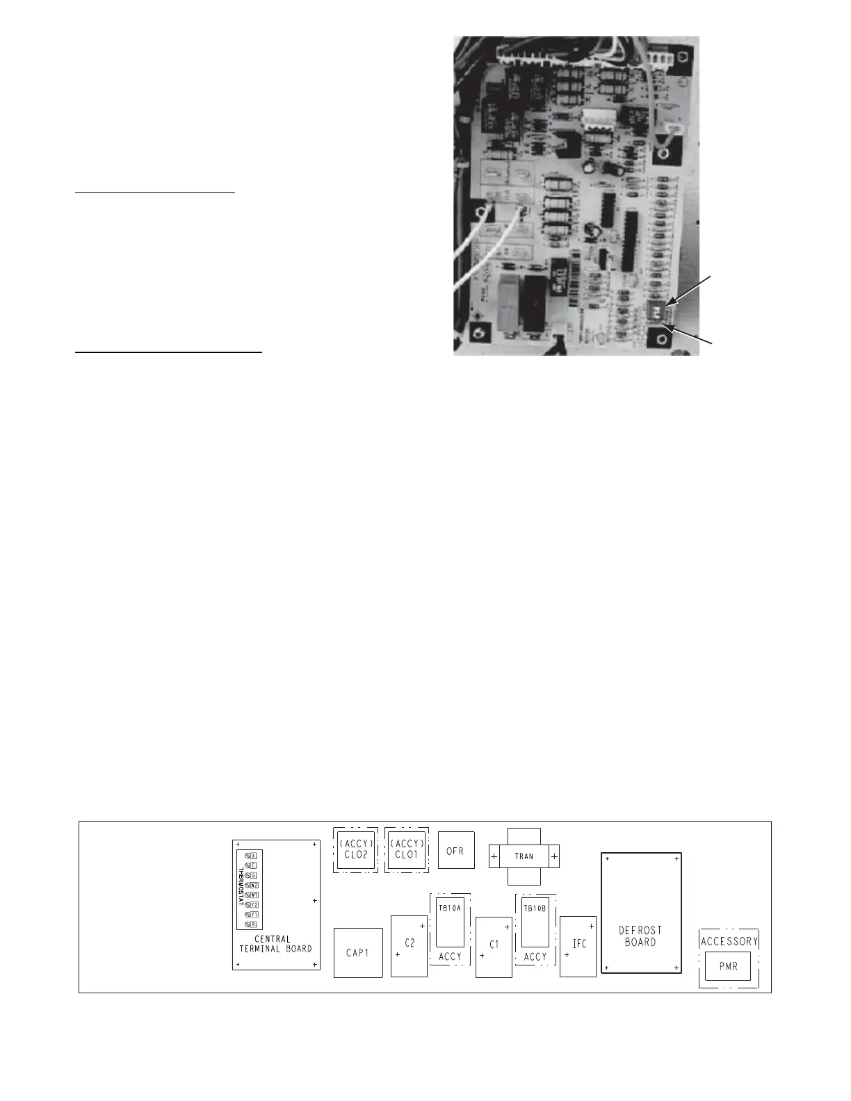
The DFB is located in the 549J’s main control box (see
Fig. 29). All connections are factory--made through
harnesses t o the unit’s CTB, to IFC (belt--drive motor) or
to ECM (direc t--drive motor), reversing valve solenoids
and to defrost thermostats. Refer to Table 5 for details of
DFB Inputs and Outputs.
Reversing valve control — The DFB has two outputs for
unit reversing valve control. Operation of the reversing
valve s is based on internal logic; this application does not
use an “O” or “B” signal to de termine reversing valve
position. Reversing valves are energized during the
cooling stages and the defrost cycle and de--energized
during heating cycles. Once energized at the start of a
cooling stage, the reversing valve will remain energized
until the next heating cycle demand is received. Once
de--energized at the start of a Heating cycle, the reversing
valves will remain de --energized until the next cooling
stage is initiated.
DIP
Switches
Speed-Up
Jumpers
C09275
Fig. 28 -- Defrost Control Board Arrangement
Compressor control — The DFB receives inputs
indicating Stage 1 Cooling, Stage 2 Cooling and Stage 1
Heating from the space thermostat or unit control system
(RTU Open controller); it generates commands to start
compressors with or without reversing valve operation to
produce Stage 1 Cooling (one compre ssor on 08--09
systems, compressor unloaded on 07 2--stage system),
Stage 2 Cooling (both compressors run on 08--09 systems,
compressor full load on 07 2--stage system) or Stage 1
Heating (both compressors run on 08--09 systems; the 07
systems have only one compressor).
Au x iliary (E lectric) Heat con t rol — The 549J unit can be
equipp ed with one or two auxiliar y electric heaters, to
provide a second stage of heating. The DFB will energize
this Heating Sys tem for a Stage 2 Heatin g Command
(heaters operate concurrently with compressor(s) in the Stage
1 Heating cycle), for an Emer g ency Heating sequ en ce
(comp res s o r s are off and only the electric heaters are
energized) and also durin g the Def ro s t cycle (to eliminate a
“cold blow” conditio n in the space).
C09276
Fig. 29 -- Defrost Control Board Location
 Loading...