21
Table 5 – 549J Defrost Board I/O and Jumper Configurations
Inputs
Point Name Type of I/O Connection Pin Number Unit Connection Note
GFan DI, 24Vac P 2 --- 3 C T B --- G
Y1 Cool 1 DI, 24Vac P 2 --- 5 C T B --- Y 1
Y2 Cool 2 DI, 24Vac P 2 --- 4 C T B --- Y 2
W1 Heat 1 DI, 24Vac P 2 --- 7 C T B --- W 1
W2 Heat 2 DI, 24Vac P 2 --- 6 C T B --- W 2
RPower 24Vac P 3 --- 1 C O N T L B R D --- 8
C Common 24V ac P 3 --- 2 C O N T L B R D --- 4
DFT1 DI, 24Vac D F T --- 1 t o D F T --- 1
DFT 2 DI, 24Vac D F T --- 2 t o D F T --- 2
Outputs
Point Name Type of I/O Connection Pin Number Unit Connection Note
IFO Fan On DO, 24Vac P 3 --- 9 R E H E A T --- 2
OF OD Fan On DO, 24Vac OF OFR
RVS1 DO, 24Vac P 3 --- 7 t o P 3 --- 5 Energize in COOL
RVS2 DO, 24Vac P 3 --- 6 t o P 3 --- 4 Energize in COOL
COMP 1 DO, 24Vac P 3 --- 1 0 F P T --- R E H E A T --- 6
COMP 2 DO, 24Vac P 3 --- 8 R E H E A T --- 8
HEAT 2 DO, 24Vac E --- H E A T H C --- 1 ( T B 4 --- 1 )
COM 24Vac P 3 --- 3 H C --- 1 ( T B 4 --- 3 )
Configuration
Point Name Type of I/O Connection Pin Number Unit Connection Note
Select Jumper 24V ac P 1 --- 1
2 Compressor 24V ac P 1 --- 3 Use for 549J*07/08/09D
Speed--Up Configuration
Point Name Type of I/O Connection Pin Number Unit Connection Note
Speed--- Up Jumper JMP17
Speed--- Up Jumper JMP18
Jumper for 1-- 3 seconds: Factory Test, defrost runs for 9 seconds
Jumper for 5--20 seconds: Forced Defrost, defrost runs for 30 seconds if DFT2 is open
Defrost — The defrost control mode is a time/temperature
sequence. There are two time components: The
continuous run peri od and the test/defrost c ycle period.
The temperature component is provi ded by Defrost
Therm ostat 1 and 2 (DFT1 and DFT2 [08--09 only])
mounted on the outdoor coil .
The continuous run period is a fixed time period between the
end of the last defros t cycle (or star t of the curren t Heatin g
cycle) during which no defro s t will be permitted. This period
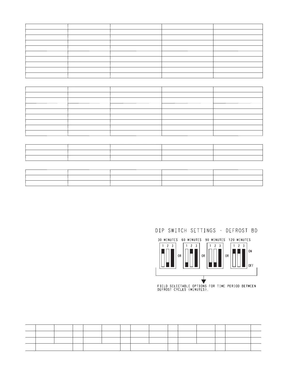
can be set at 30, 60, 90 or 120 minutes by changing the
positions of DIP switches SW1 and SW2 (see Fig. 30 and
Table 6). The default run periods are 30 minutes for unit size
07 and 90 minutes for unit sizes 08--09.
Shorting the jumpers for a period of 5 t o 20 secs bypasses
the remaining con tinuous run period and places the unit in
a Forced Defrost mode. If the controlling DFT is closed
when this mode is initiated, the unit will complete a
normal defrost period that will terminate when the
controlling DFT opens or the 10 minute defrost cycle limit
is reached. If the controlling DFT is open when this mode
is initiated, the Defrost cycle will run for 30 secs. Both
modes end at the end of t he Defrost cyc le.
C09283
Fig. 30 -- DIP Switch Settings — Defrost Board
Table 6 – Dip Switch Position
Switch No.
1 2 1 2 1 2 1 2 3
1 J 1 J 1 1 J J 1 On
0 J 0 J 0 J J 0 0 J Off
30 minutes 60 minutes
90 minutes
120 minutes Fan Delay
 Loading...