25
Outputs —
Actuator signal: 2 --10 Vdc; minimum actuator impedance
is 2k ohm; bus t wo--wire output for bus communicating
actuators.
Exhaust fan, Y1, Y2 and AUX1 O:
All Relay Outputs (at 30 Vac):
Running: 1.5A maximum
Inrush: 7.5A maximum
Environmental —
Operating Temperature: --40 to 150_F (--40 to 65_C).
Exception of display operation down to --4_F with full
recovery at --4_F from exposure to --40_F
Storage Temperature: --40 to 150_F (--40 to 65_C)
Shipping Temperature: --40 to 150_F (--40 to 65_C)
Relative Humidity: 5% to 95% RH non--condensing
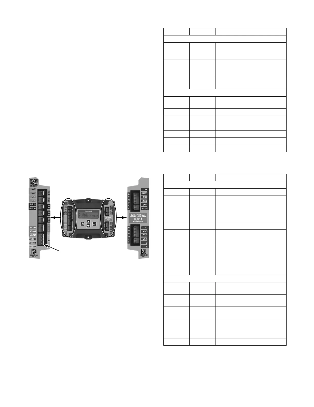
Economizer Module Wiring Details —
Use Fig. 38 and Tables 8 and 9 to locate t he wiring
terminals for the economizer module.
NOTE: The four terminal blocks are removable. You can
slide out each terminal block, wire it, and then slide it
back into place.
W7220 Controller
Left Terminal
Block Label
Right Terminal
Block Label
NOTE: The bottom 4 Pin actuator header is not used
C14156
Fig. 38 -- W7220 Economizer Module Terminal
Connection Labels
S--Bus Sensor Wiring —
The labels on the sensors and controller are color coded
for ease of installation. Orange labeled sensors can only
be wired to orange terminals on the controller. Brown
labeled sensors can only be wired to S--Bus (brown)
terminals. Use Fig. 39 and Ta ble 10 t o locate the wiring
terminals for each S--Bus sensor.
Use Fig. 39 and Table 11 to set the DIP switches for the
desired use of the sensor.
Table 8 – Economizer Module --
Left Hand Terminal Blocks
Label Type Description
Top Left Terminal Block
MAT
MAT
20k NTC
and
COM
Supply Air Temperature Sensor
(polarity insensitive connection)
OAT
OAT
20k NTC
and
COM
Outdoor Air Temperature Sensor
(polarity insensitive connection)
S --- B U S
S --- B U S
S --- B u s
(Sylk* Bus)
Enthalpy Control Sensor
(polarity insensitive connection)
Bottom Left Terminal Block
I A Q 2 --- 1 0 2 --- 1 0 V d c Air Q uality Sensor Input
(e.g. CO
2
sensor)
IAQ COM COM Air Q uality Sensor C ommon
IAQ 24V 24 Vac Air Quality Sensor 24 Vac Source
A C T 2 --- 1 0 2 --- 1 0 V d c Damper Actuator Output (2--- 10 Vdc)
ACT COM COM Damper Actuator Output Common
ACT 24V 24 Vac Damper Actuator 24 Vac Source
n/a The bottom pin is not used.
Table 9 – Economizer Module --
Right Hand Terminal Blocks
Label Type Description
Top R ig ht Te r mi na l B lo c k
n/a The first pin is not used
AUX2 I 24 Vac IN Shut Down (SD) or Heat (W)
Conventional only
or
Heat Pump Changeover (O/B) in
Heat Pump mode.
OCC 24 V ac IN Occupied / Unoccupied Input
E --- G N D E --- G N D Earth Ground --- System Required
EXH1 24 Vac OUT Exhaust Fan 1 Output
AUX1 O 24 Vac OUT Programmable:
Exhaust fan 2 output
or
ERV
or
System Alarm output
Bottom Right Terminal Block
Y 2 --- I 24 Vac IN Y2 in --- Cooling Stage 2 Input from
space thermostat
Y 2 --- O 24 Vac OUT Y2 out --- Cooling Stage 2 Output to
stage 2 mechanical cooling
Y 1 --- I 24 Vac IN Y1 in --- Cooling Stage 1 Input from
space thermostat
Y 1 --- O 24 Vac OUT Y1 out --- Cooling Stage 1 Output to
stage 1 mechanical cooling
C COM 24 Vac Common
R 24 Vac 24 Vac Power (Hot)
* Sylk is a trademark of Honeywell International Inc.
 Loading...