42
EconoMi$e r 2 —
The RTU Open controller is used with EconoMi$er2
(option or accessory) for outdoor air management. The
damper position is controlled directly by the RTU Open
controller; E conoMi$er2 has no internal logic device.
Outdoor air management functions can be enhanced with
field--installation of these accessory control devices:
Enthalpy control (outdoor air or differential sensors)
Space CO
2
sensor
Outdoor air CO
2
sensor
Field Connections
Field c onnections for accessory sensors a nd input devices
are made to the RTU Open controller at plugs J1, J2, J4,
J5, J11 and J20. All fie ld control wiring that connec ts to
the RTU Open controller must be routed through the
raceway built into the corner post as shown in Fig. 31.
The raceway provides the UL required clearance between
high-- and low--voltage wiring. Pass the control wires
through the hole provided in the corner post, the n feed the
wires t hrough the raceway to the RTU Open controller.
Connect to the wires to the removable PCB connectors
and then rec onnect the connectors to the board.
Space Temperature (SPT) Sensors —
SPT sensors a vailable from Bryant are resistive input
non-communicating (T55, T56, and T59) sensors. These
sensors have a variety of options consisting of: timed
override button, set point adjustm ent, and a LCD screen.
Space temperature can be also be written to from a
building network or zoning system. However, it is still
recom mended that return air duct sensor be installed to
allow stand-alone operation for back-up. Refer to the
configuration section for details on controller
configurations associat ed with space sensors.
S 33ZCT55SPT, space temperature sensor with override
button
S 33ZCT56SPT, space temperature sensor with override
button and setpoint adjustment
S 33ZCT59SPT, space temperature sensor with LCD
(liquid crystal displa y) screen, override button, and
setpoint adjustment
Use 20 gauge wire to connect the sensor to the controller.
The wire is suitable for distances of up to 500 ft. Use a
three--conductor shielded cable for t he sensor and setpoint
adjustment connections. If the setpoint adjustment
(slidebar) is not required, then an unshielded, 18 or 20
gauge, t wo--conductor, twisted pair ca ble may be used.
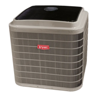
Connect T-- 55: See Fig. 46 for typical T--55 internal
connec tions. Connect the T--55 SEN termina ls to the RTU
Open controller at J20--1 and J20--2. See Fig. 47.
2
3
45
61
SW1
SEN
BRN (GND)
BLU (SPT)
RED(+)
WHT(GND)
BLK(-)
CCN COM
SENSOR WIRING
C08201
Fig. 46 -- T--55 Space Temperature Sensor Wiring
SEN
SEN
J20-1
J20-2
C08460
Fig. 47 -- RTU Open Controller T--55 Sensor
Connections
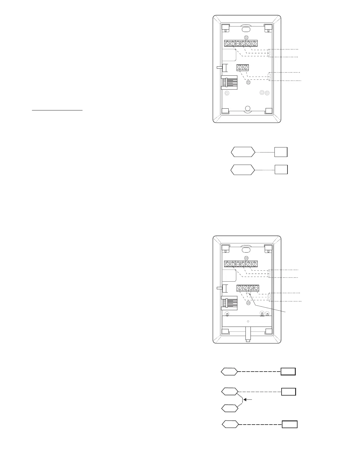
Connect T --56: See Fig. 48 for T--56 internal connections.
Install a jumper between SEN and SET terminals as
illustrated. Connect T--56 terminals to the RTU Open
controller at J20--1, J20--2 and J20 --3 per Fig. 49.
2
3
45
61
SW1
SEN
SET
Cool Warm
BRN (GND)
BLU (SPT)
RED(+)
WHT(GND)
BLK(-)
CCN COM
SENSOR WIRING
JUMPER
TERMINALS
AS SHOWN
BLK
(T56)
C08202
Fig. 48 -- T--56 Internal Connections
SEN J20-1
J20-2
SEN
SET
Jumper
J20-3
SET
C08461
Fig. 49 -- RTU Open Controller T--56 Sensor
Connections
 Loading...