III. ENTHALPY CONTROL CHECKOUT PROCEDURES
A. Solid-State Enthalpy Control
Use this procedure for the solid-state enthalpy control that
comes standard with the economizer. (See table below.)
Solid-State Enthalpy Control Contents
PART NO.
HF25CA003
Economizer Motor
Economizer Logic Module
HH57AC078 Solid-Stage Enthalpy Sensor
HH79AZ001 Mixed-Air Sensor
1. Disconnect power at terminals TR and TR1. Dis-
connect jumper across terminals P and P1.
2. Jumper terminals TR and 1.
3. Connect enthalpy sensor to terminals SO and +. The
factory-installed 620-ohm resistor should be in place
on terminals SR and +.
4. Turn enthalpy set point to ‘‘A.’’
5. Jumper terminal T to terminal T1.
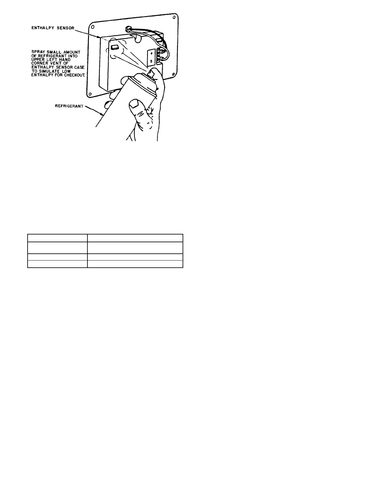
6. Spray a small amount of refrigerant in the upper left
vent of the enthalpy sensor to simulate low enthalpy
conditions. (See Fig. 15.)
7. Connect 24-v power at terminals TR and TR1. The LED
(light-emitting diode) will turn on and the economizer
motor will drive the damper full open.
8. Disconnect the jumper at terminals T and T1. The econo-
mizer motor will drive the damper full closed.
9. Connect a jumper across terminals P and P1.
10. Turn minimum position potentiometer adjustment coun-
terclockwise and the economizer motor drives the damper
closed.
11. Turn minimum position potentiometer adjustment clock-
wise and the economizer motor drives the damper open.
12. Disconnect the power at terminals TR and TR1. The
economizer motor spring-returns the damper to closed
position.
B. Differential Enthalpy Control
Use this checkout procedure for the accessory differential
enthalpy control. The differential enthalpy control kit con-
tains one solid-state enthalpy sensor (part no. HH57AC078)
to be installed in addition to the solid-state enthalpy control
which comes standard with the economizer. See table on
this page for standard solid-state enthalpy control package
contents.
1. Disconnect the power at terminals TR and TR1. See
Fig. 12.
2. Disconnect the jumper across terminals P and P1.
3. Disconnect the factory-installed 620-ohm resistor.
4. Connect one enthalpy sensor to terminals SO and +.
5. Connect the other enthalpy sensor to terminals SR
and +.
6. Turn the enthalpy set point past the ‘‘D’’ setting (fully
clockwise).
7. Connect a jumper across terminals T and T1.
8. Spray a small amount of refrigerant in upper left vent
of enthalpy sensor connected to SO and + to simulate
low outdoor-air enthalpy. (See Fig. 15.)
9. Reconnect power at terminals TR and TR1. The LED
(Light-emitting diode) turns on, and the economizer
motor drives the damper open.
10. Spray a small amount of refrigerant in upper left vent
of enthalpy sensor connected to SR and + to simulate
low return-air enthalpy. (See Fig. 15.) The LED turns
off, and the economizer motor drives the damper closed.
Fig. 15 — Use of Refrigerant Spray on Sensor to
Simulate Low Enthalpy
—7—