FLUE HOOD
REQ’D CLEARANCES FOR OPERATION AND SERVICING. in. (mm)
Evaporator coil access side .....................36(914)
Power entry side (except for NEC requirements) ............36(914)
Unit top ............................48(1219)
Side opposite ducts ........................36(914)
Duct panel ...........................12(304.8)*
*Minimum distances: If unit is placed less than 12 in. (304.8 mm) from wall system, then
the system performance may be compromised.
REQ’D CLEARANCES TO COMBUSTIBLE MAT’L. in. (mm)
Top of unit ...........................14(355.6)
Duct side of unit ..........................2(50.8)
Side opposite ducts .......................14(355.6)
Bottom of unit .........................0.50 (12.7)
Flue panel ...........................36(914.4)
NEC REQ’D CLEARANCES. in. (mm)
Between units, power entry side ..................42(1066.8)
Unit and ungrounded surfaces, power entry side ............36(914)
Unit and block or concrete walls and other grounded
surfaces, control box side ....................42(1066.8)
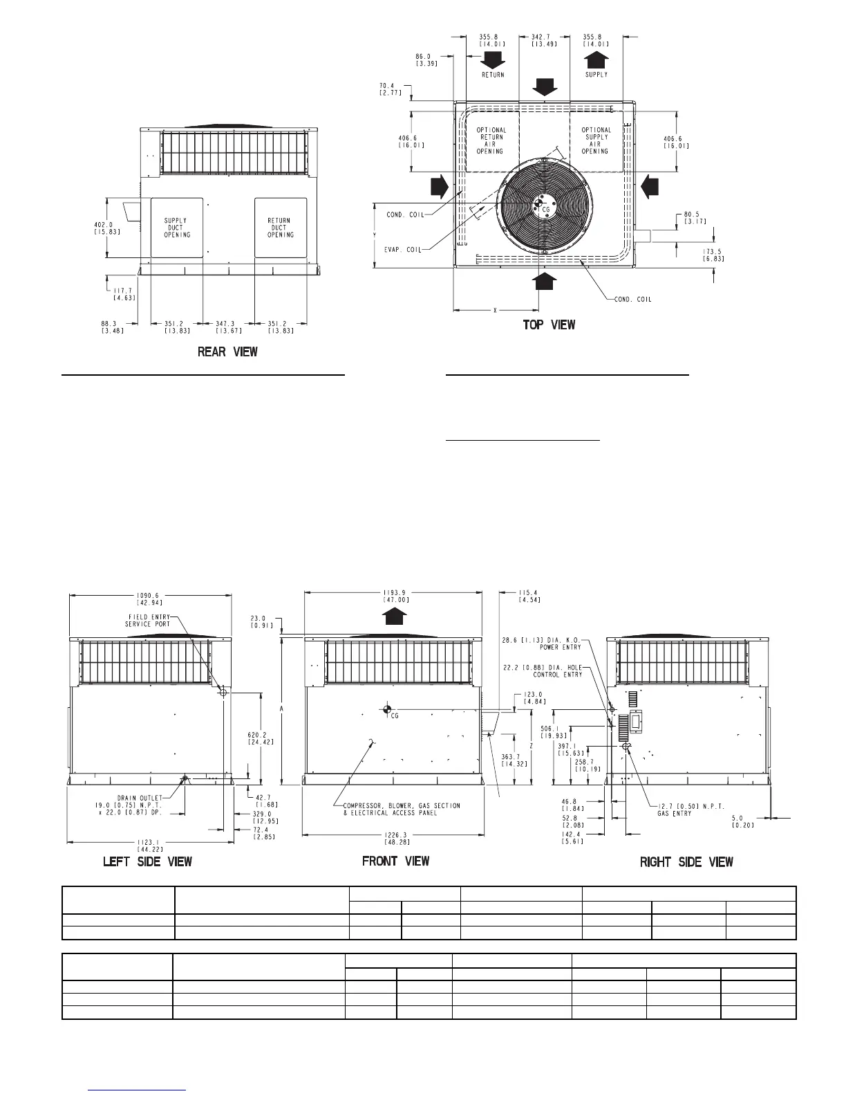
LEGEND
CG — Center of Gravity
COND — Condenser
EVAP — Evaporator
NEC — National Electrical Code
REQ’D — Required
NOTE: Dimensions are in mm [in.]
UNIT
ELECTRICAL
CHARACTERISTICS
UNIT WEIGHT UNIT HEIGHT in. [mm] CENTER OF GRAVITY in. [mm]
lb kg A X Y Z
582A048090/115/130 208-230/1/60, 208/230-3-60, 460-3-60 415 188.6 38.98 [990.2] 22 [558.5] 16 [406.4] 17 [432.0]
582A060090/115/130 208/230-1-60, 208/230-3-60, 460-3-60 450 204.5 38.98 [990.2] 22 [558.5] 16 [406.4] 17 [432.0]
UNIT
ELECTRICAL
CHARACTERISTICS
UNIT WEIGHT UNIT HEIGHT in. [mm] CENTER OF GRAVITY in. [mm]
lb kg A X Y Z
583A042060/090 208/230-1-60, 208/230-3-60, 460-3-60 382.0 842.2 38.98 [990.2] 23.0 [584.2] 16.3 [412.8] 16.6 [421.6]
583A048090/115/130 208/230-1-60, 208/230-3-60, 460-3-60 421.0 928.2 38.98 [990.2] 21.5 [546.1] 16.6 [422.1] 18.0 [457.2]
583A060090/115/130 208/230-1-60, 208/230-3-60, 460-3-60 468.0 1031.7 42.98 [1091.7] 23.5 [596.9] 16.3 [412.8] 17.6 [447.0]
Fig. 3 — 582A048,060 and 583A042,048,060 Unit Dimensions
—3—
 Loading...