CAUTION: Installation of filter drier in liquid line is
required.
B. INSTALL LIQUID-LINE FILTER DRIER
Installation of filter drier in liquid line is required. Refer to Fig. 5
and install filter drier as follows:
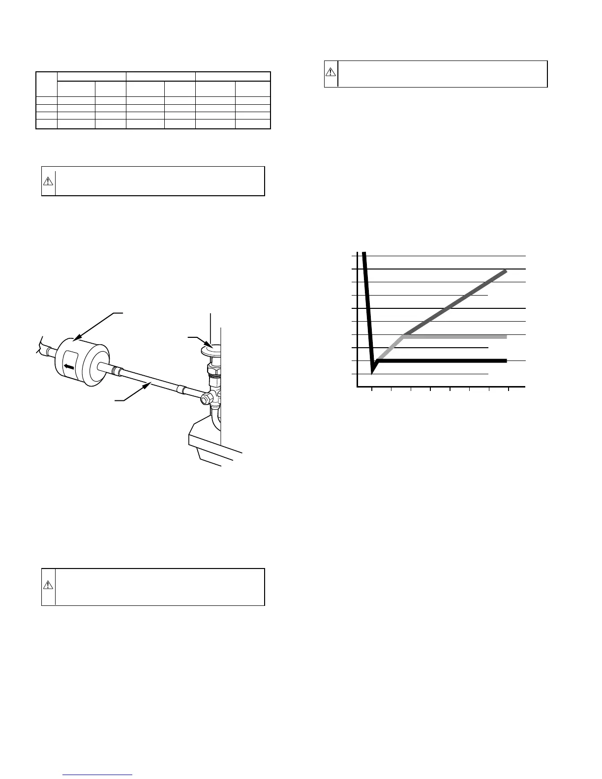
1. Braze 5–in. connector tube to liquid service valve. Wrap
filter drier with damp cloth.
2. Braze filter drier between connector tube and liquid tube to
indoor coil. Flow arrow must point toward indoor coil.
C. REFRIGERANT TUBING
Connect vapor tube to fitting on outdoor unit vapor service valves.
Connect liquid tube to filter drier. (See Fig. 5 and Table 1.) Use
refrigerant grade tubing.
CAUTION: To avoid valve damage while brazing, ser-
vice valves must be wrapped in heat-sink material, such
as a wet cloth.
D. SWEAT CONNECTION
Service valves are closed from factory and ready for brazing. After
wrapping service valve and filter drier with a wet cloth, tubing set
can be brazed to service valve and filter drier using either silver
bearing or non-silver bearing brazing material. Consult local code
requirements. Refrigerant tubing and indoor coil are now ready for
leak testing. This check should include all field and factory joints.
IMPORTANT: Check factory tubing on both indoor and outdoor
unit to ensure tubes are not rubbing against each other or any sheet
metal. Pay close attention to feeder tubes making sure wire ties on
feeder tubes are secure and tight.
E. EVACUATE REFRIGERANT TUBING AND INDOOR
COIL
CAUTION: Never use the system compressor as a
vacuum pump.
Refrigerant tubes and indoor coil should be evacuated using the
recommended deep vacuum method of 500 microns. The alternate
triple evacuation method may be used if the procedure outlined
below is followed. Always break a vacuum with dry nitrogen.
DEEP VACUUM METHOD
The deep vacuum method requires a vacuum pump capable of
pulling a vacuum of 500 microns and a vacuum gage capable of
accurately measuring this vacuum depth. The deep vacuum
method is the most positive way of assuring a system is free of air
and liquid water. (See Fig. 6.)
TRIPLE EVACUATION METHOD
The triple evacuation method should only be used when vacuum
pump is capable of pumping down to 28 in. of mercury and system
does not contain any liquid water. Refer to Fig. 7 and proceed as
follows:
1. Pump system down to 28 in. of mercury and allow pump to
continue operating for an additional 15 minutes.
2. Close service valves and shut off vacuum pump.
3. Connect a nitrogen cylinder and regulator to system and
open until system pressure is 2 psig.
4. Close service valve and allow system to stand for 1 hr.
During this time, dry nitrogen will be able to diffuse
throughout the system, absorbing moisture.
5. Repeat this procedure as indicated in Fig. 7. System will
then contain minimal amounts of contaminants and water
vapor.
F. FINAL TUBING CHECK
IMPORTANT: Check to be certain factory tubing on both indoor
and outdoor unit has not shifted during shipment. Ensure tubes are
not rubbing against each other or any sheet metal. Pay close
attention to feeder tubes, making sure wire ties on feeder tubes are
secure and tight.
TABLE 1—REFRIGERANT CONNECTIONS AND
RECOMMENDED LIQUID AND VAPOR TUBE
DIAMETERS (IN.)
UNIT
SIZE
LIQUID VAPOR VAPOR (LONG-LINE)
Connection
Diameter
Tube
Diameter
Connection
Diameter
Tube
Diameter
Connection
Diameter
Tube
Diameter
024 3/8 3/8 5/8 5/8 5/8 3/4
036 3/8 3/8 3/4 3/4 3/4 7/8
048 3/8 3/8 7/8 7/8 7/8 7/8
060 3/8 3/8 7/8 1-1/8 7/8 1-1/8
Notes:
1. Tube diameters are for lengths up to 50 equivalent ft.
2. Do not apply capillary tube indoor coils to these units.
Fig. 5—Filter Drier with Sweat Adapter Tube and Liquid
Tube
A95509
LIQUID-LINE
FILTER-DRIER
CONNECTOR
TUBE
R
-
4
1
0
A
LIQUID
SERVICE
VALVE
Fig. 6—Deep Vacuum Graph
A95424
500
MINUTES
01234567
1000
1500
LEAK IN
SYSTEM
VACUUM TIGHT
TOO WET
TIGHT
DRY SYSTEM
2000
MICRONS
2500
3000
3500
4000
4500
5000
A95424
—4—