VII. MAKE ELECTRICAL CONNECTIONS
WARNING: To avoid personal injury or death, do not
supply power to unit with compressor terminal box cover
removed.
Be sure field wiring complies with local and national fire, safety,
and electrical codes, and voltage to system is within limits shown
on unit rating plate. Contact local power company for correction of
improper voltage. See unit rating plate for recommended circuit
protection device.
NOTE: Operation of unit on improper line voltage constitutes
abuse and could affect unit reliability. See unit rating plate. Do not
install unit in system where voltage may fluctuate above or below
permissible limits.
NOTE: Use copper wire only between disconnect switch and
unit.
NOTE: Install branch circuit disconnect of adequate size per
NEC to handle unit starting current. Locate disconnect within sight
from and readily accessible from unit, per Section 440-14 of NEC.
A. ROUTE GROUND AND POWER WIRES
Remove access panel to gain access to unit wiring. Extend wires
from disconnect through power wiring hole provided and into unit
control box. Size wires per NEC but not smaller than minimum
wire size shown in Product Data Sheet.
WARNING: The unit cabinet must have as uninter-
rupted or unbroken ground to minimize personal injury if
an electrical fault should occur. The ground may consist
of electrical wire or metal conduit when installed in
accordance with existing electrical codes. Failure to
follow this warning can result in an electric shock, fire, or
death.
B. CONNECT GROUND AND POWER WIRES
Connect ground wire to ground connection in control box for
safety. Connect power wiring to leads provided as shown in Fig. 8.
C. CONNECT CONTROL WIRING
Route 24v control wires through control wiring grommet and
connect to leads provided in control box. (See Table 3 and Fig. 9.)
Use No. 18 AWG color-coded, insulated (35°C minimum) wire. If
thermostat is located more than 100 ft from unit, as measured
along the control voltage wires, use No. 16 AWG color-coded wire
to avoid excessive voltage drop.
All wiring must be NEC Class 1 and must be separated from
incoming power leads.
The outdoor unit requires a minimum of 27va, 24vac control
power.
IMPORTANT: Check factory wiring and wire connections to
ensure terminations are secured properly. Check wire routing to
ensure wires are not in contact with tubing, sheet metal, etc.
VIII. INSTALL ELECTRICAL ACCESSORIES
A. GENERAL
Refer to the individual instructions packaged with kits or acces-
sories when installing.
Available electrical accessories include latent capacity control. See
Table 3 and Fig. 9 for typical accessory wiring diagrams.
B. LATENT CAPACITY CONTROL (LCC)
The purpose of an LCC is to provide a dehumidification mode to
assure a 75 percent or less system sensible heat ratio. If indoor unit
installed contains an ICM blower (such as an FK4C or FV4A fan
coil or a 333(B,J)AV or 355MAV gas furnace), no LCC is
required. Indoor products with ICM blowers have enough CFM
range to provide proper airflow for low-speed cooling. If indoor
unit installed has a standard PSC blower motor, the low-speed
airflow available is too great to assure 75 percent or less system
sensible heat ratio. The LCC for standard blower products consists
of a standard humidistat which opens contacts on humidity rise and
a pilot duty relay with 24v coil.
NOTE: If an LCC is desired, low-speed airflow must be main-
tained so that a minimum of 300 CFM/ton can be supplied during
high-speed LCC operation.
LCC OPERATION FOR TYPICAL PSC FAN COILS
The standard blower operation for systems with typical PSC fan
coils is covered in Fig. 9A, B, and D. The blower runs in high
speed regardless if compressor operation is high or low speed.
When the LCC is wired according to Fig. 9A, B, or D and humidity
rises, the humidistat contacts open and de-energize the relay. If
relay is de-energized, the system operates on high-speed compres-
sor and high-speed airflow until humidistat closes. Fig. 9C shows
the wiring with a Bryant Thermidistat which controls temperature
and humidity level without the need for an additional humidistat
and relay.
LCC OPERATION FOR TYPICAL PSC FURNACES
The standard blower operation of systems with typical PSC
furnaces is covered in Fig. 9J, K, M, N, P, and R. The blower runs
in high or low speed in conjunction with compressor high- or
low-speed operation. When the LCC is wired according to Fig. 9K,
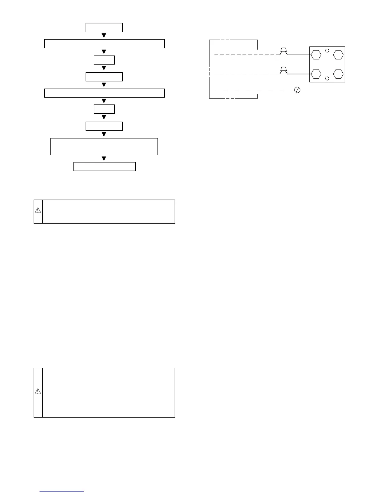
Fig. 7—Triple Evacuation Method
A95425
CHECK FOR TIGHT, DRY SYSTEM
(IF IT HOLDS DEEP VACUUM)
EVACUATE
BREAK VACUUM WITH DRY NITROGEN
WAIT
EVACUATE
CHARGE SYSTEM
BREAK VACUUM WITH DRY NITROGEN
EVACUATE
WAIT
Fig. 8—Line Power Connections
A91306
CONTACTOR
DISCONNECT
PER N. E. C. AND/ OR
LOCAL CODES
FIELD POWER
WIRING
FIELD GROUND
WIRING
GROUND
LUG
—5—
 Loading...