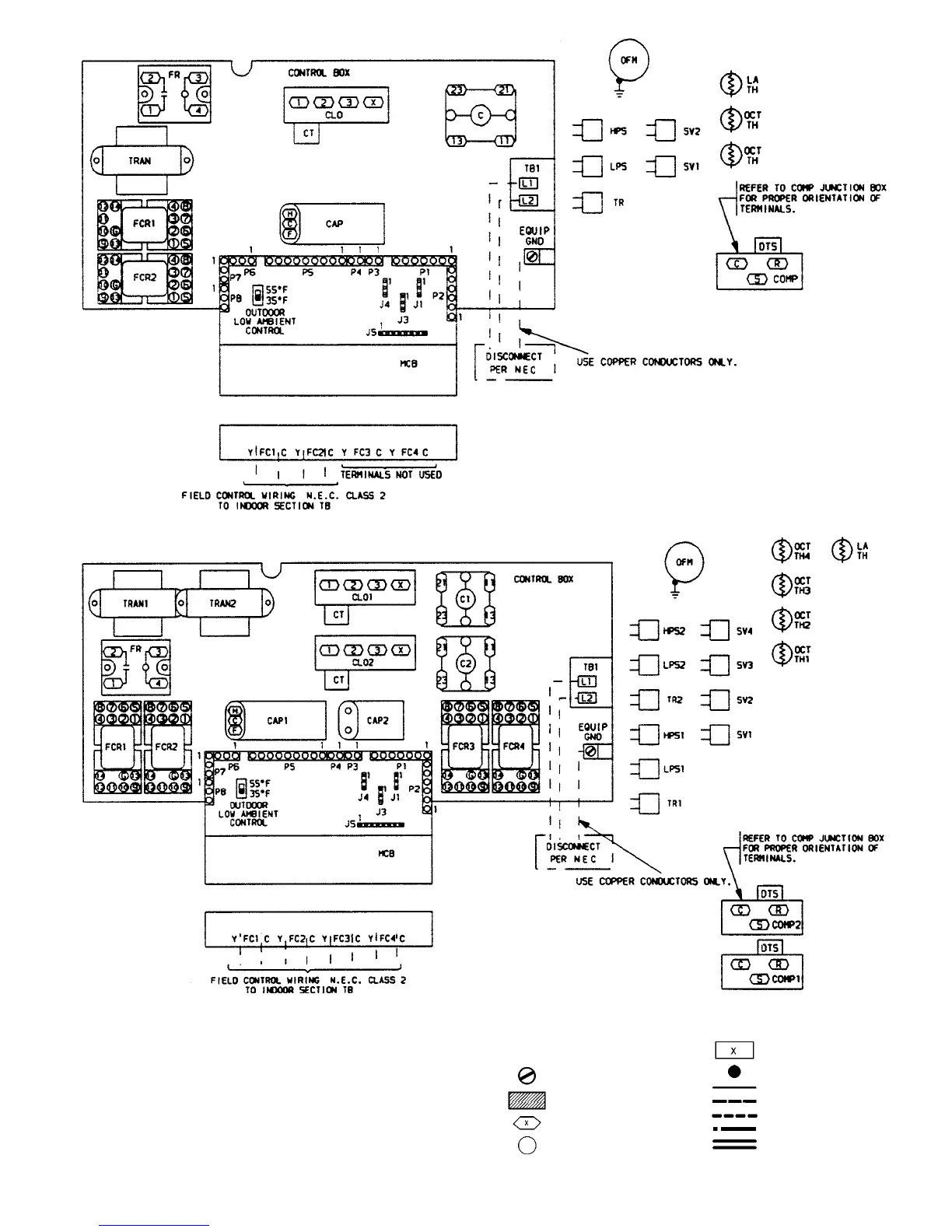
Fig. 10 — Component Arrangement, 538S
_
024
Fig. 11 — Component Arrangement, 538S
_
048
LEGEND FOR FIG. 10 AND 11
C—Contactor, Compressor
CAP — Capacitor
CLO — Compressor Lock Out
COMP — Compressor Motor
CT — Current Transformer
DTS — Discharge Temperature
Switch
EQUIP — Equipment
FC — Fan Coil Unit
FCR — Fan Coil Relay
FR — Fan Relay
GND — Ground
HPS — High-Pressure Switch
J—Connector
LPS — Low-Pressure Switch
LA — Low Ambient
MCB — Multi-Split Control Board
NEC — National Electrical Code
OCT — Outdoor Coil Temperature
OFM — Outdoor-Fan Motor
P—Connector
SV — Solenoid Valve
TB — Terminal Block
TH — Themistor
TR — Transducer
TRAN — Transformer
Terminal (PCB, Field)
Terminal (PCB, Factory)
Terminal (Marked)
Terminal (Unmarked)
Terminal Block
Splice
Factory Wiring
Field Control Wiring
Field Power Wiring
Option or Accessory Wire
PCB Run
—11—
 Loading...