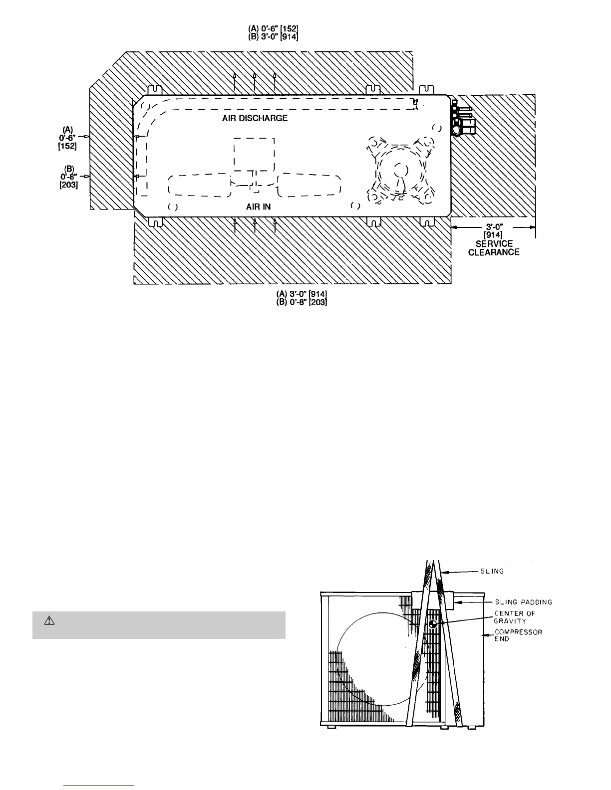
Unit may be mounted on a level pad directly on base legs or
mounted on raised pads at support points. See Fig. 2 and 4
for center of gravity.
II. INSTALL OUTDOOR UNIT
A. Mounting on Ground
Mount unit on a solid, level concrete pad. Position unit so
water or ice from roof does not fall directly onto unit. If con-
ditions or local codes require unit be fastened to pad, 6 field-
supplied tiedown bolts should be used and fastened through
slots provided in unit mounting feet. See Fig. 2.
B. Mounting on Roof
Mount unit on a level platform or frame at least 6 in.
(154 mm) above roof surface. Isolate unit and tubing from
structure.
C. Surrounding Fences and Walls
Select and install surrounding fences and walls to allow for
free entry of ambient air. Avoid pits and solid walls as unit
surroundings, because recirculation of warm discharge air can
occur.
D. Rigging
CAUTION:
Be sure unit panels are securely in place
prior to rigging.
Keep unit upright. Lift unit using sling. Use cardboard or pad-
ding under sling, and use spreader bars to prevent sling dam-
age to unit. See Fig. 4. See Fig. 2 and 4 for center of gravity
reference. Install unit so that coil does not face into prevail-
ing winds. If this is not possible and constant winds above
25 mph are expected, field fabricate and install wind baffles.
In areas where outdoor ambient will be less than 40 F during
cooling, wind baffles are also required. Contact your local rep-
resentative for drawings and assembly details.
III. INSTALL FAN COIL UNITS
Refer to Installation, Start-Up and Service Instructions pro-
vided with the fan coil units.
NOTE: If this system is mixing 2 or more types of fan coil
units, be sure to follow instructions provided with each type
of fan coil unit closely.
Mount fan coil units in locations which will be easily acces-
sible when routing refrigerant tubing (see Fig. 5 and 6) and
electrical wiring between the fan coil units and outdoor unit.
Fan coil unit locations must also provide adequate drainage
capabilities. If desired, condensate pumps may be used with
any type of fan coil unit.
IMPORTANT: DO NOT install filter driers or AccuRatert re-
frigerant metering device body or pistons into this system.
TXVs are located in the outdoor condensing unit to control
refrigerant flow.
Fig. 4 — Lifting Unit With Sling
NOTE: Dimensions in [ ] are in mm.
(A) Minimum operating clearance required when this side faces a wall.
(B) Minimum operating clearance required when this side faces away from a wall.
Fig. 3 — Operating and Service Clearance
—4—
 Loading...