IV. COMPLETE REFRIGERANT PIPING
NOTE: Complete all refrigerant tubing connections at the fan
coil units first. Then route the tubing sets back to the out-
door unit. Mark each tubing set carefully to identify its re-
spective fan coil unit.
Outdoor units may be connected to indoor units using field-
supplied tubing of refrigerant grade and condition. See
Table 1 for correct line sizes. Do not use less than 10 ft
of interconnecting tubing.
NOTE: It is not necessary to make any changes to line sizes
or any refrigerant system modifications when using recom-
mended refrigerant line lengths.
When installing tubing, both the vapor return line and the
vapor supply (smaller) line must be insulated between out-
door unit and indoor unit to avoid condensation on the lines.
Use closed-cell foam insulation and tape all seams and joints.
CAUTION:
DO NOT BURY MORE THAN 36 IN. OF
REFRIGERANT TUBING IN THE GROUND. If any sec-
tion of tubing is buried, there must be a 6-in. vertical
rise to the valve connections on the outdoor unit. If more
than the recommended length is buried, refrigerant may
migrate to cooler, buried section during extended peri-
ods of system shutdown. This causes refrigerant slug-
ging and could possibly damage compressor at start-
up.
DO NOT USE MORE THAN 50 FT of EQUIVALENT
interconnecting tubing or more than 30 ft of VERTI-
CAL lift (see Fig. 7) between the lowest system compo-
nent and the highest system component.
If either refrigerant tubing or indoor coil is opened to atmo-
spheric conditions for longer than 5 minutes, it must be evacu-
ated to 1000 microns to eliminate contamination and mois-
ture in the system.
Run refrigerant tubes as directly as possible, avoiding un-
necessary turns and bends. Suspend refrigerant tubes so they
do not damage insulation on vapor return or supply tubes
and do not transmit vibration to structure. Also, when pass-
ing refrigerant tubes through wall, seal opening so that vi-
bration is not transmitted to structure. Leave some slack in
refrigerant tubes between structure and outdoor unit to ab-
sorb vibration. See Fig. 5 for indoor to outdoor unit tubing
connections, and refer to separate indoor fan coil unit instal-
lation instructions for additional information.
NOTE: If only 2 fan coil units are used on 538S
_
048 sys-
tems, be sure that one is used with each compressor refrig-
erant circuit. If 2 or 3 fan coil units are used, cap any unused
refrigerant lines at the service valves.
WARNING:
DO NOT INSTALLAFIELD-SUPPLIED
FILTER DRIER in this system. Filter drier is factory
installed inside the outdoor unit. Installing a filter drier
in the liquid line between the indoor and outdoor units
will cause a high-pressure drop, and will result in ab-
normal system operation.
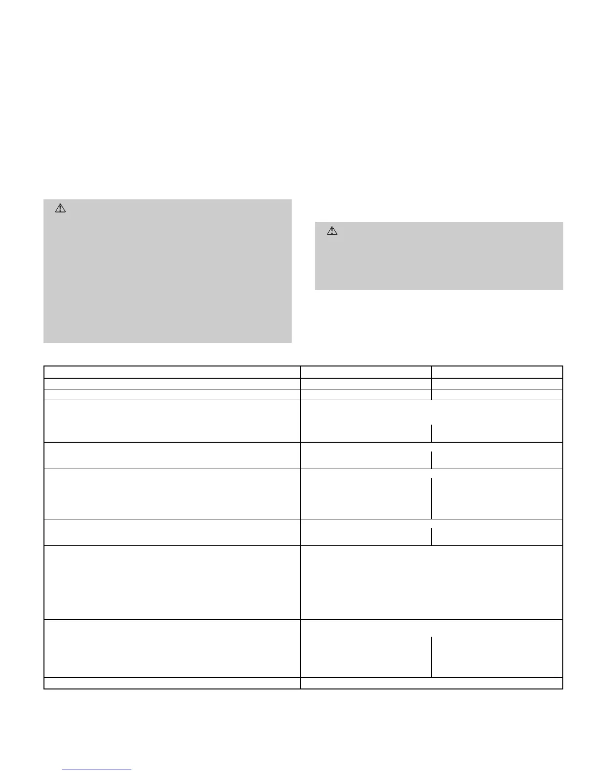
Table 1 — Specifications
UNIT 538S
_
024 048
NOMINAL CAPACITY (Tons) 24
OPERATING WEIGHT (lb) 159 292
REFRIGERANT TYPE R-22
Control (Cooling) TXV in Condensing Unit
Factory Charge (lb)*
Circuit A 5.0 5.5
Circuit B — 5.5
COMPRESSOR TYPE Copeland Scroll
Quantity...Model 1...ZR23K1 2...ZR49K3
Oil (Recharge) (oz) 25 53
OUTDOOR FAN Propeller, Direct Drive
Rpm 850 850
Diameter (in.)...No. of Blades 18...3 24...3
Pitch (Degrees) 27 24
Motor Hp
1
⁄
8
1
⁄
4
Nominal Air Cfm 1720 3900
OUTDOOR COIL Copper Tube, Aluminum Fin
Face Area (sq ft)...No. of Rows 6.1...2 12.3...2
Fins/in. 15 15
CONTROLS
High-Pressure (psig)
Cut-in 320±20
Cutout 426 ± 7
Low-Pressure (psig)
Cut-in 22 ± 5
Cutout 7± 3
Fusible Plug 210 F
Control Voltage 24
REFRIGERANT LINES
Connection Type Sweat
Vapor Supply Line Quantity...OD (in.) 2...
3
⁄
8
2†...
3
⁄
8
Vapor Return Line Quantity...OD (in.) 2...
5
⁄
8
2†...
7
⁄
8
Maximum Length (ft) 50 50
Maximum Lift (Fan Coil Above Outdoor) (ft) 30** 30**
Maximum Lift (Fan Coil Below Outdoor) (ft) 30** 30**
EXTERNAL FINISH Alpine Mist (Beige)
LEGEND
TXV — Thermostatic Expansion Valve
*Charge is based on 25 ft of interconnecting line.
†Per circuit.
**Maximum system lift is 30 ft between lowest system component and
highest system component.
—7—
 Loading...