Increased Demand for Cooling
NOTE: There are 2 separate compressor circuits in the
538S
_
048 units (circuit A and circuit B). Each circuit oper-
ates independently, and will operate as follows (as will the
single-circuit 024 units) upon receiving the first 24-v cooling
demand signal from a fan coil unit:
1. After the 2-minute time-delay function is satisfied, the
appropriate compressor starts.
2. The solenoid valve connected to the fan coil sending the
demand signal is energized (at the 538S units).
3. The outdoor fan starts, and its operation is controlled
by the microprocessor as described in 538S Microproces-
sor Control of Outdoor Fan section below.
When a second fan coil unit signals a demand for cooling, its
associated solenoid valve is energized immediately, allowing
refrigerant to flow to both fan coil units simultaneously.
Decreased Demand for Cooling
When a fan coil unit’s demand for cooling ends, the 24-v sig-
nal to the 538S unit stops, and the appropriate solenoid valve
closes. If the other fan coil unit on this circuit still has a de-
mand, the appropriate compressor will continue to run as long
as necessary for the second fan coil unit.
When the second fan coil unit’s demand for cooling ends, its
solenoid valve closes, and the appropriate compressor stops.
The compressor will not start for at least 2 minutes after the
end of this cycle due to the time-delay function.
On size 024 units, when the compressor stops, the outdoor
fan also stops. On size 048 units, outdoor fan operation may
continue under control of the 538S microprocessor if the other
refrigerant circuit is still operating. The outdoor fan will only
stop when both compressors are off. Refer to 538S Micro-
processor Control of Outdoor Fan section below for more
details.
C. 538S Microprocessor Control of Outdoor Fan
The microprocessor control has a built-in head pressure con-
trol system that will cycle the outdoor-fan motor to maintain
a selected discharge pressure. The microprocessor senses out-
door ambient temperature using a thermistor and refriger-
ant pressure using a pressure transducer mounted on the
compressor circuit discharge line. The 538S
_
024 units have
one transducer, and the 048 units have two.
The factory set points for the head pressure control opera-
tion are 55 F for outdoor ambient temperature and 250 psig
for discharge pressure.
When the outdoor ambient temperature is above the outdoor
ambient set point and both fan coils on a compressor circuit
are calling for cooling operation, the outdoor fan will run at
full speed whenever compressor operation is permitted. When
only one fan coil on a circuit is calling for cooling, fan cycling
is permitted at all ambients. Fan motor will be cycled on and
off to maintain set point discharge pressure.
When the outdoor ambient temperature is below the speci-
fied set point, the fan motor will be cycled on and off to main-
tain a compressor discharge pressure at the specified pres-
sure set point. On 538S
_
048 units with 2 compressors running,
the compressor with the lower head pressure will control the
fan operation. If only one compressor is running, that com-
pressor will control the fan operation.
If the discharge pressure on either circuit exceeds 370 psig,
the outdoor-fan motor will run continuously, and the fan cy-
cling function will be bypassed until the discharge pressure
decreases to 365 psig.
Units can be field configured to select head pressure control
at 35 F outdoor ambient and/or 200 psig discharge pressure.
D. Status Indicator Lights
The 538S control board is equipped with LED indicators to
aid in evaluating the status of the control system, including
(see Table 3):
• time delay function status
• fan coil unit demand status
• head pressure control status
• current unit malfunctions
E. Unit Malfunction
Each compressor circuit is equipped with a high-pressure switch
(HPS), a loss-of-pressure switch (LPS), and a discharge tem-
perature switch (DTS). These safety devices are located in a
Cycle-LOC™ device circuit that prevents compressor opera-
tion if any of these safety devices is activated. The lockout
can be reset by turning the main power to the 538S unit off,
then on again.
Compressor overcurrent protection is achieved by an inter-
nal linebreak overload, which will automatically reset when
the motor temperature cools to a satisfactory level. Manual
reset of Cycle-LOC circuit may also be required (turn main
unit disconnect to OFF, then to ON position).
Pressure transducers and the outdoor ambient thermistor are
monitored by the 538S controller. If a pressure transducer is
found to be out of range, the LEDs will flash a code for this
fault, but the control will continue to cycle the outdoor fan
according to input from the other transducer. If only one trans-
ducer is active and is determined to be out of range, the head
pressure control will be bypassed and the fan will run con-
tinuously. If the thermistor is found to be out of range, the
control will allow fan cycling per transducer input, and the
LEDs will flash a code for this failure. See Table 3.
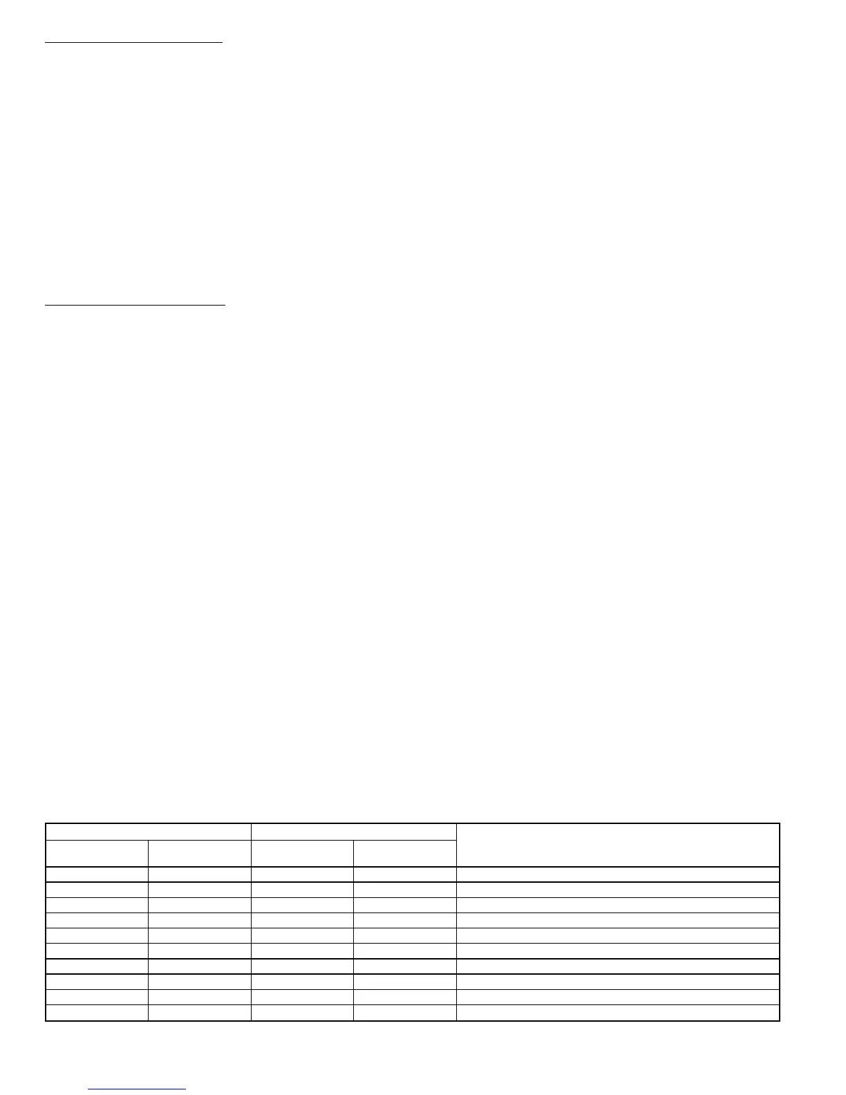
Table 3 — System Status Red and Green LEDs and Fault Codes
GREEN LED RED LED
UNIT STATUS
Number of
Flashes On
Number of
Flashes Off
Number of
Flashes On
Number of
Flashes Off
1 1 — Always Off System Ready
1111 LowHead Pressure, Circuit 1
1122 High Head Pressure, Circuit 1
1133 LowHead Pressure, Circuit 2
2211 High Head Pressure, Circuit 2
2222LowOutdoor Ambient Temperature, Outdoor Thermistor
2233High Outdoor Ambient Temperature, Outdoor Thermistor
3311 Hardware Error
3322 TimeGuardT Device Active, Circuit 1
3333 TimeGuard Device Active, Circuit 2
LED — Light-Emitting Diode
—14—
 Loading...