CAUTION: Unit failure as a result of operation on
improper line voltage or excessive phase imbalance con-
stitutes abuse and may cause damage to electrical com-
ponents. Do not install units in system where voltage
may fluctuate above or below permissible limits. Such
operation would invalidate any applicable warranty.
A. Outdoor Condensing Unit
Be sure field wiring complies with local and national fire, safety,
and electrical codes, and that voltage to the system is within
limits shown in Table 2. Contact local power company for cor-
rection of improper line voltage.
See Table 2 for recommended fuse sizes. When making elec-
trical connections, provide clearance at unit for refrigerant
piping connections.
B. Install Branch Circuit Disconnect Per NEC
Install a disconnect of adequate size to handle unit starting
current. Locate disconnect within sight from and readily ac-
cessible from unit per Section 440-14 of NEC.
C. Route Line Power Leads
Extend leads from disconnect through power wiring hole pro-
vided and into unit splice area. Remove outdoor unit control
box cover to gain access to unit wiring.
NOTE: Power leads from disconnect into outdoor unit must
be COPPER WIRE ONLY.
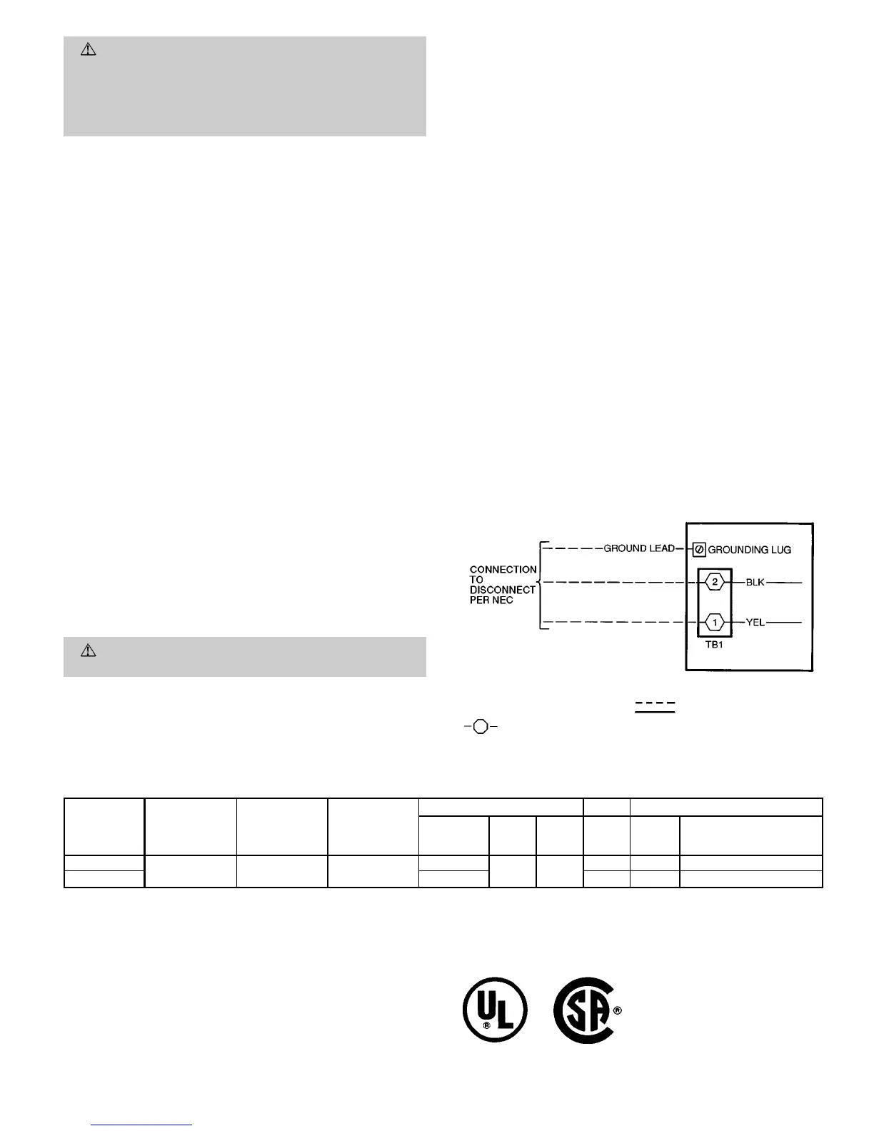
D. Connect Ground Lead and Power Wiring
Connect ground lead to equipment ground connection in out-
door unit control box. Then connect power wiring to TB1
(terminal block no. 1). See Fig. 8. Splice the line power leads
to yellow and black leads provided.
E. Indoor Unit
Refer to installation instructions included with the fan coil
units for fan coil unit installation and power supply details.
F. Connect Control Circuit Wiring
WARNING:
To avoid personal injury, be sure system
main power switch is turned off before proceeding.
1. Refer to Multi-Split Installation Planning Worksheet com-
pleted prior to the start of this installation and verify
the markings on each set of control wiring cable sets.
2. Route 24-v control wiring through wiring hole on the out-
door unit. See Fig. 9 for typical connections for each type
of fan coil. See. Fig. 10 and 11 for 538S component ar-
rangement and unit wiring details. See Fig. 12 for 538S
to fan coil unit control wiring connection details.
3. Connect wiring to screw connections labeled FC1, FC2,
FC3, and FC4 on terminal board for each corresponding
fan coil unit. See Fig. 9-12.
4. Route the other end of the control wiring back to the
fan coil unit and connect to the fan coil terminal board
according to the wiring schematic for the fan coil unit.
See fan coil unit installation instructions for wiring
schematic.
G. Connect Thermistor Wiring
1. Refer to fan coil unit installation instructions for loca-
tion of thermistor harness assemblies (not used on 619F
units). The installation instructions are shipped with each
fan coil unit. Connect the outdoor unit thermistor har-
ness plugs at the matching fan coil unit terminal blocks.
2. Label each thermistor harness per the previously com-
pleted Multi-Split Installation Planning Worksheet.
3. Route the thermistor harness assemblies from the out-
door unit to the indoor fan coil units.
IMPORTANT: DO NOT RUN THE THERMISTOR
CABLES IN THE SAME CONDUIT AS THE CON-
TROL CIRCUIT OR POWER WIRING.
4. Route harnesses into 538S unit junction box.
5. Connect each thermistor plug to its matching plug in
the outdoor condensing unit.
Table 2 — Electrical Data
UNIT SIZE
538S
_
V-PH-Hz
OPERATING
VOLTAGE
MINIMUM*
OPERATING
VOLTAGE
MAXIMUM*
COMPRESSOR FAN POWER SUPPLY
Quantity
RLA
(Ea)
LRA
(Ea)
FLA MCA
Max Fuse
or HACR-Type
Circuit Breaker Amps
024
208/230-1-60 187 254
1
12.9 62.5
0.70 16.8 25
048 2 1.45 30.5 40
LEGEND
FLA — Full Load Amps
HACR — Heating, Air Conditioning, Refrigeration
LRA — Locked Rotor Amps
MCA — Minimum Circuit Amps
NEC — National Electrical Code
RLA — Rated Load Amps (Compressor)
*Permissible limits of the voltage range at which unit will operate
satisfactorily.
NOTES:
1. The 538S units contain a 24-v transformer; additional transformers
are not required.
2. All motors and compressors contain internal overload protection.
3. In compliance with NEC requirements for multimotor and combina-
tion load equipment (refer to NEC Articles 430 and 440), the over-
current protective device for the unit shall be fuse or HACR breaker.
4. Motor RLA values are established in accordance with UL (Underwrit-
ers’ Laboratories) Standard 1995.
LEGEND
NEC — National Electrical Code
Field Wiring
TB — Terminal Board
Factory Wiring
TB Connections
Fig. 8 — Line Power Connections
—9—
 Loading...