1. Install suction tube adapter.
2. Install liquid flare-to-sweat adapter.
3. Connect external equalizer tube to fitting on suction tube
adapter.
4. Position sensing bulb on horizontal portion of suction tube
adapter. Secure using supplied hardware.
5. Insulate bulb after installation. (See Fig. 6.)
6. Leak check all connections.
B. Fan Coils
If indoor unit (fan coil) comes factory equipped with a bi-flow
hard shutoff TXV specifically designed for Puron, no TXV change
is required.
If TXV installation is required, refer to TXV kit Installation
Instructions for details on TXV installation.
VII. CHECK DEFROST THERMOSTAT
Check defrost thermostat to ensure it is properly located and
securely attached. There is a liquid header with a brass distributor
and feeder tube going into outdoor coil. At the end of 1 of the
feeder tubes, there is a 3/8-in. OD stub tube approximately 3 in.
long. (See Fig. 7.) The defrost thermostat should be located on stub
tube. Note that there is only 1 stub tube used with liquid header,
and on most units it is the bottom circuit.
VIII. IN LONG-LINE APPLICATIONS, INSTALL LIQUID-
LINE SOLENOID VALVE (LSV)
For refrigerant piping arrangements with equivalent lengths
greater than 50 ft and/or when elevation difference between indoor
and outdoor unit is greater than ± 20 ft, follow all requirements of
the Long-Line Guideline section in the Application Guideline and
Service Manual for Residential Split-System Air Conditioners and
Heat Pumps Using Puron Refrigerant.
If required by Long-Line Application Guideline, install LSV kit
Part No. KHALS0401LLS specifically designed for Puron Heat
Pump. LSV should be installed within 2 ft of outdoor unit with
flow arrow pointing toward outdoor unit. Follow the Installation
Instructions included with accessory kit.
IMPORTANT: Flow arrow must point toward outdoor unit.
IX. MAKE PIPING CONNECTIONS
WARNING: Relieve pressure and recover all refrigerant
before system repair or final unit disposal to avoid
personal injury or death. Use all service ports and open all
flow-control devices, including solenoid valves.
CAUTION: Do not leave system open to atmosphere
any longer than minimum required for installation. POE
oil in compressor is extremely susceptible to moisture
absorption. Always keep ends of tubing sealed during
installation.
CAUTION: If ANY refrigerant tubing is buried, provide
a 6 in. vertical rise to the valve connections at the unit. Do
NOT bury refrigerant tubing lengths greater than 36 in.
CAUTION: To prevent damage to unit or service valves
observe the following:
• Use a brazing shield.
• Wrap service valves with wet cloth or use a heat sink
material.
Outdoor units may be connected to indoor section using accessory
tubing package or field-supplied refrigerant grade tubing of correct
size and condition. For tubing requirements beyond 50 ft, substan-
tial capacity and performance losses can occur. Follow the
recommendations in the Application Guideline and Service
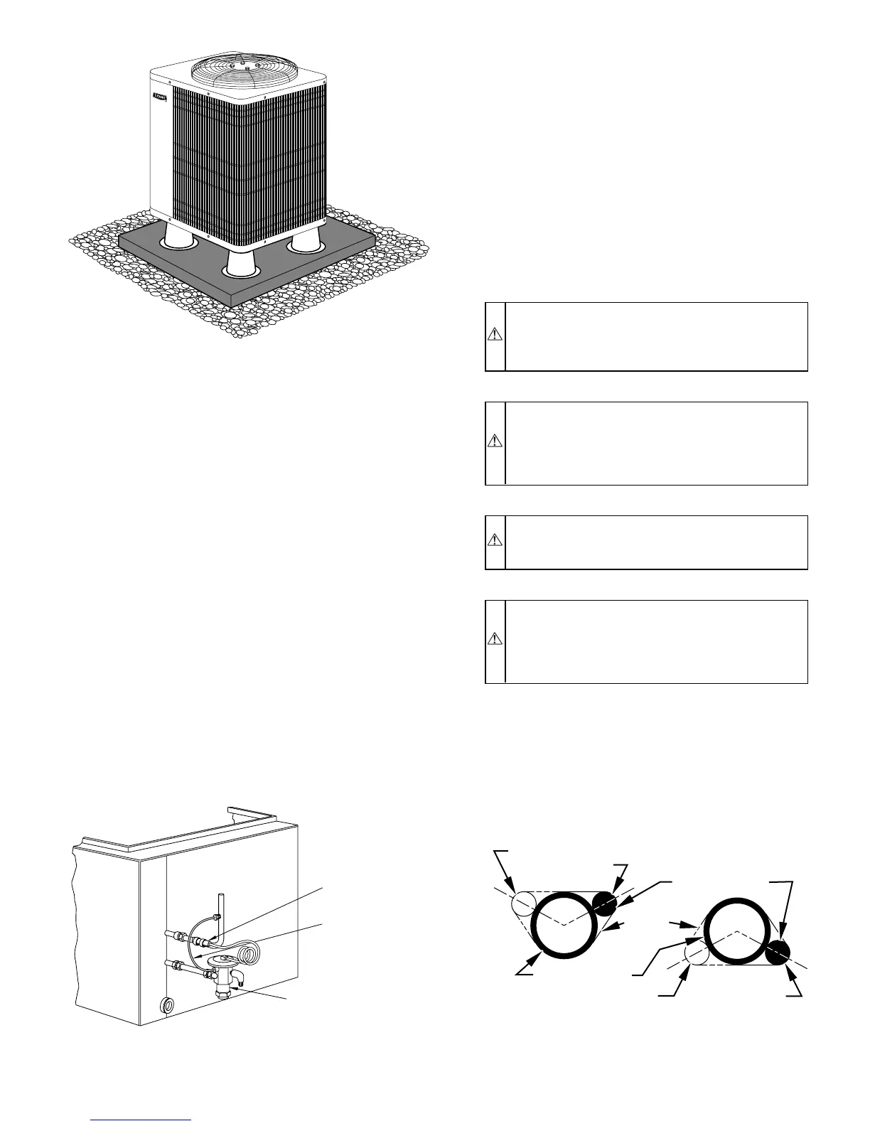
Fig. 4—Accessory Support Feet
A98532
Fig. 5—Typical TXV Installation
A91277
THERMOSTATIC
EXPANSION
VALVE
EQUALIZER
TUBE
SENSING
BULB
COIL
Fig. 6—Positioning of Sensing Bulb
A81032
2 O'CLOCK
10 O'CLOCK
SENSING BULB
STRAP
SUCTION TUBE
8 O'CLOCK
4 O'CLOCK
7
⁄
8
IN. OD & SMALLER
LARGER THAN
7
⁄
8
IN. OD
—3—