EXAMPLE:
To calculate additional charge required for a 25-ft line set:
25 ft - 15 ft = 10 ft X 0.6 oz/ft=6ozofadditional charge
Units installed with cooling mode TXV require charging with the
subcooling method.
1. Operate unit a minimum of 10 minutes before checking
charge.
2. Measure liquid service valve pressure by attaching an
accurate gage to service port.
3. Measure liquid line temperature by attaching an accurate
thermistor type or electronic thermometer to liquid line near
outdoor coil.
4. Refer to Heat Pump Charging Instructions label on outdoor
unit for required subcooling temperature.
5. Refer to Table 3. Find the point where required subcooling
temperature intersects measured liquid service valve pres-
sure.
6. To obtain required subcooling temperature at a specific
liquid line pressure, add refrigerant if liquid line tempera-
ture is higher than indicated or reclaim refrigerant if
temperature is lower. Allow a tolerance of ± 3°F.
C. Heating Check Charge Procedure
To check system operation during heating cycle, refer to the Heat
Pump Charging Instructions label on outdoor unit. This chart
indicates whether a correct relationship exists between system
operating pressure and air temperature entering indoor and outdoor
units. If pressure and temperature do not match on chart, system
refrigerant charge may not be correct. Do not use chart to adjust
refrigerant charge.
NOTE: In heating mode, check refrigerant charge only when
pressures are stable. If in doubt, remove charge and weigh in
correct refrigerant charge.
NOTE: When charging is necessary during heating season,
charge must be weighed in accordance with unit rating plate ± 0.6
oz/ft of 3/8-in. liquid line above or below 15 ft respectively.
EXAMPLE:
To calculate additional charge required for a 25-ft line set:
25 ft - 15 ft = 10 ft X 0.6 oz/ft=6ozofadditional charge
XV. FINAL CHECKS
IMPORTANT: Before leaving job, be sure to do the following:
1. Securely fasten all panels and covers.
2. Tighten service valve stem caps to 1/12-turn past finger
tight.
3. Leave User’s Manual with owner. Explain system operation
and periodic maintenance requirements outlined in manual.
4. Fill out Dealer Installation Checklist and place in customer
file.
CARE AND MAINTENANCE
For continuing high performance and to minimize possible equip-
ment failure, periodic maintenance must be performed on this
equipment.
Frequency of maintenance may vary depending upon geographic
areas, such as coastal applications.
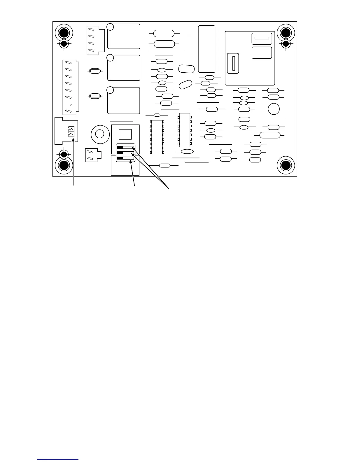
Fig. 14—Defrost Control
A99442
OF2
CESO130076–00
OF1
ON
QUIET
SHIFT
120
30
60
60
30
90
INTERVAL TIMER
OFF
P3
DFT
O R W
2
Y C
T2 C C O
DFT
T1 Y
P1
J1
SPEEDUP
Speedup
Pins
Defrost interval
DIP switches
Quiet
Shift
—8—