800SA/801SA: Installation, Start–Up, Operating and Service and Maintenance Instructions
Manufacturer reserves the right to change, at any time, specifications and designs without notice and without obligations.
30
7. Adjust blower off delay The blower off delay has 4 adjustable
settings from 90 sec to 180 sec. The blower off delay jumpers are
located on the furnace control board (see Fig. 28).
To change the blower off delay setting, move the jumper from one
set of pins on the control to the pins used for the selected blower off
delay. Factory off delay setting is 120 sec.
8. Set airflow CFM for cooling
Select the desired blower motor speed lead for cooling airflow. See
Table 4-Air Delivery-CFM (With Filter) for lead color
identification.
Check Safety Controls
The flame sensor, gas valve, and pressure switch were all checked in the
Start-up procedure section as part of normal operation.
1. Check Main Limit Switch(es)
This control shuts off combustion control system and energizes
air-circulating blower motor, if furnace overheats. By using this
method to check limit control, it can be established that limit is
functioning properly and will operate if there is a restricted duct
system or motor failure. If limit control does not function during
this test, cause must be determined and corrected.
a. Run furnace for at least 5 minutes.
b. Gradually block off return air with a piece of cardboard or sheet
metal until the limit trips.
c. Unblock return air to permit normal circulation.
d. Burners will re-light when furnace cools down.
2. Check draft safeguard switch.
The purpose of this control is to cause the safe shutdown of the
furnace during certain blocked vent conditions.
a. Verify vent pipe is cool to the touch.
b. Disconnect power to furnace and remove vent connector from
furnace vent elbow.
c. Restore power to furnace and set room thermostat above room
temperature.
d. After normal start-up, allow furnace to operate for 2 minutes,
then block vent elbow in furnace 80 percent of vent area with a
piece of flat sheet metal.
e. Furnace should cycle off within 2 minutes. If gas does not shut
off within 2 minutes, determine reason draft safeguard switch did
not function properly and correct condition.
f. Remove blockage from furnace vent elbow.
g. Switch will auto-reset when it cools.
h. Re-install vent connector.
NOTE: Should switch remain open longer than 3 minutes, furnace
control board will lockout the furnace for 3 hours. To reset furnace
control board, turn thermostat below room temperature or from HEAT to
OFF and turn 115v power OFF, then back ON.
3. Check Pressure Switch
This control proves operation of the draft inducer blower.
a. Turn off 115-v power to furnace.
b. Disconnect inducer motor lead wires from wire harness.
c. Turn on 115-v power to furnace.
d. Set thermostat to “call for heat” and wait 1 minute. When
pressure switch is functioning properly, hot surface igniter
should NOT glow and control diagnostic light flashes a status
code 31. If hot surface igniter glows when inducer motor is
disconnected, shut down furnace immediately.
e. Determine reason pressure switch did not function properly and
correct condition.
f. Turn off 115-v power to furnace.
g. Reconnect inducer motor wires, replace outer door, and turn on
115-v power.
h. Blower will run for 90 sec before beginning the call for heat
again.
i. Furnace should ignite normally.
Checklist
1. Put away tools and instruments. Clean up debris.
2. Verify that blower OFF-DELAY time is selected as desired.
3. Verify that blower and burner access doors are properly installed.
4. Cycle test furnace with room thermostat.
5. Check operation of accessories per manufacturer’s instructions.
6. Review User’s Guide with owner.
7. Attach literature packet to furnace
.
SERVICE AND MAINTENANCE PROCEDURES
Untrained personnel can perform basic maintenance functions such as
cleaning and replacing air filters. All other operations must be performed
by trained service personnel. A qualified service person should inspect
the furnace once a year.
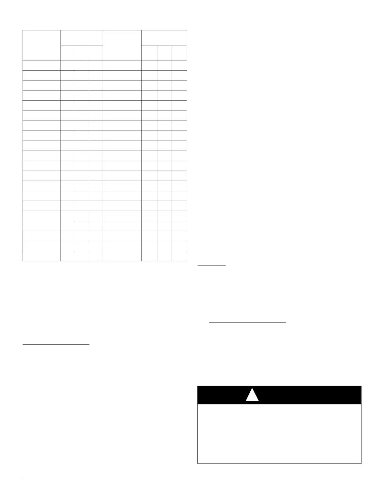
30 120 240 600 80 45 90 225
31 116 232 581 82 44 88 220
32 113 225 563 84 43 86 214
33 109 218 545 86 42 84 209
34 106 212 529 88 41 82 205
35 103 206 514 90 40 80 200
36 100 200 500 92 39 78 196
37 97 195 486 94 38 76 192
38 95 189 474 96 38 75 188
39 92 185 462 98 37 74 184
40 90 180 450 100 36 72 180
41 88 176 439 102 35 71 178
42 86 172 429 104 35 69 173
43 84 167 419 106 34 68 170
44 82 164 409 108 33 67 167
45 80 160 400 110 33 65 164
46 78 157 391 112 32 64 161
47 76 153 383 116 31 62 155
48 75 150 375 120 30 60 150
49 73 147 367
Table 13 – Gas Rate (Cu Ft./Hr.) (Continued)
SECONDS
FOR 1
REVOLUTION
SIZE OF TEST
DIAL
SECONDS
FOR 1
REVOLUTION
SIZE OF TEST
DIAL
1 Cu
Ft.
2 Cu
Ft.
5 Cu
Ft.
1 Cu
Ft.
2 Cu
Ft.
5 Cu
Ft.
WARNING
!
FIRE, INJURY, OR DEATH HAZARD
Failure to follow this warning could result in personal injury, death
and/or property damage.
The ability to properly perform maintenance on this equipment requires
certain knowledge, mechanical skills, tools, and equipment. If you do
not possess these, do not attempt to perform any maintenance on this
equipment other than those procedures recommended in the User’s
Manual.