810SA/811SA: Installation, Start–Up, Operating and Service and Maintenance Instructions
Manufacturer reserves the right to change, at any time, specifications and designs without notice and without obligations.
13
1. A filter is required for each return-air inlet. Airflow performance included 3/4-in. (19 mm) washable filter (see accessory list). To determine airflow performance without this filter, assume an
additional 0.1 In. W.C. available external static pressure.
2. Adjust the blower speed tabs as necessary for the proper air temperature rise for each installation.
3. -- Indicates unstable operating conditions.
4. If the same motor speed tap is needed for heating and cooling, a Jumper Wire accessory kit is available. (See Product Data sheet for the current Jumper Wire accessory part number). See
Function column for applicable limitations.
A190084
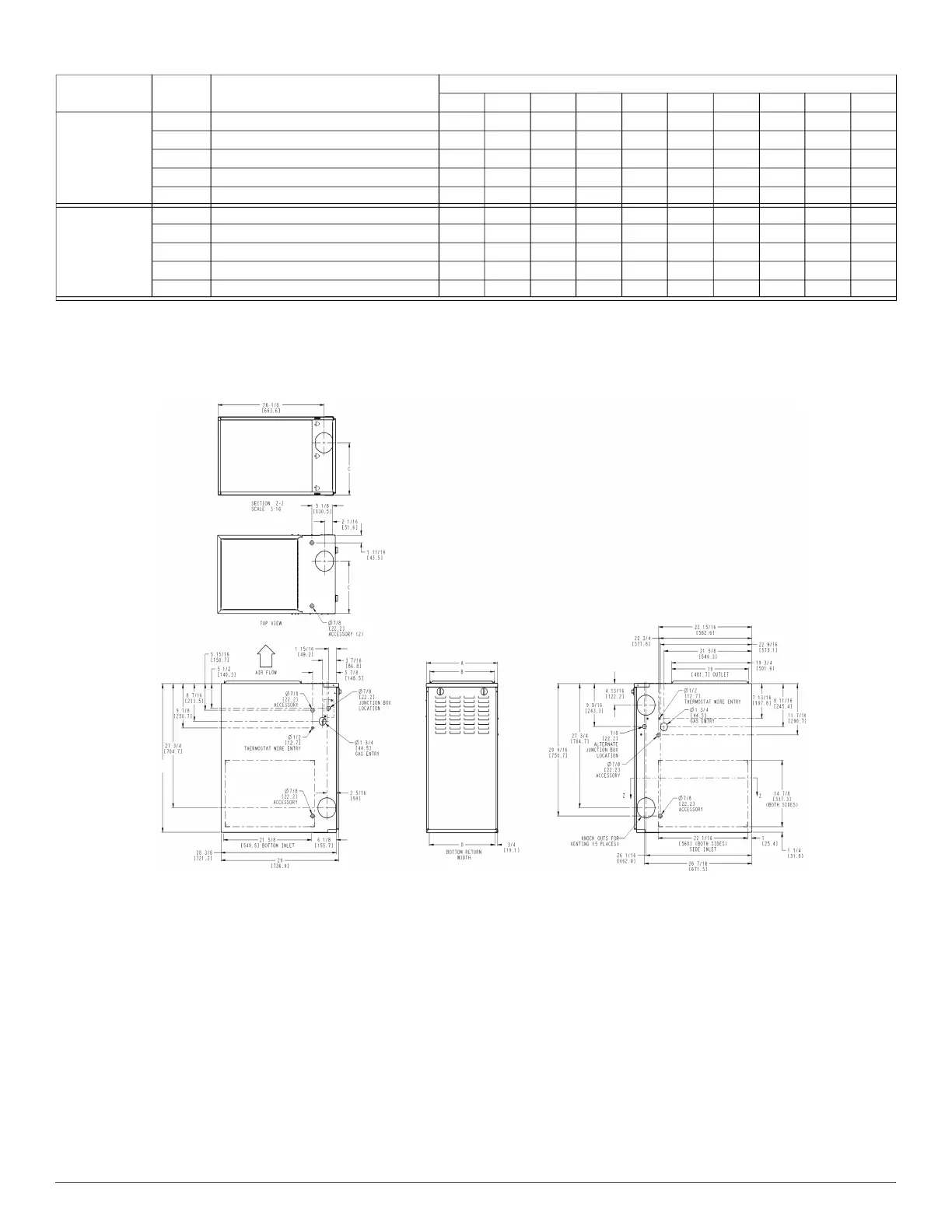
NOTES:
1. Two additional 7/8-in. (22 mm) diameter holes are located in the top plate.
2. Minimum return-air openings at furnace, based on metal duct. If flex duct is used, see flex duct manufacturer’s recommendations for equivalent diameters.
a. For 800 CFM-16-in. (406 mm) round or 14 1/2 x 12-in. (368 x 305 mm) rectangle.
b. For 1200 CFM-20-in. (508 mm) round or 14 1/2 x 19 1/2-in. (368 x 495 mm) rectangle.
c. For 1600 CFM-22-in. (559 mm) round or 14 1/2 x 22 1/16-in. (368 x 560mm) rectangle.
d. For airflow requirements above 1800 CFM, see Air Delivery table in Product Data Sheet literature for specific use of single side inlets. The use of both side inlets, a combination of 1
side and the bottom, or the bottom only will ensure adequate return air openings for airflow requirements above 1800 CFM.
Fig. 17 – Dimensional Drawing
60110E24
Gray Cooling. Do not use for heating. 2250 2190 2130 2070 2005 1950 1885 1820 1755 1685
Blue Heating or alt Cooling 1995 1930 1865 1800 1740 1670 1605 1535 1465 1400
Yellow Alt Cooling or alt Heating 1540 1460 1385 1305 1235 1165 1095 1035 955 890
Orange Alt Cooling. Do not use for heating. 1345 1195 1135 1055 980 920 845 770 695 620
Red Alt Cooling. Do not use for heating. 1335 1075 965 890 820 735 660 580 505 440
60135E24
Gray Cooling. Do not use for heating. 2065 2005 1940 1875 1810 1740 1670 1600 1530 1470
Blue Heating or alt Cooling 1825 1760 1695 1630 1560 1490 1420 1350 1275 1205
Yellow Alt Cooling or alt Heating 1760 1690 1625 1555 1485 1415 1345 1275 1200 1130
Orange Alt Cooling. Do not use for heating. 1620 1550 1480 1405 1335 1260 1195 1130 1065 995
Red Alt Cooling. Do not use for heating. 1325 1260 1185 1100 1025 955 885 805 735 670
Table 4 – Air Delivery - CFM (With Filter)* (Continued)
Furnace
Wire Lead
Color
Function
Test Airflow Delivery @ Various External Static Pressures
0.1 0.2 0.3 0.4 0.5 0.6 0.7 0.8 0.9 1
33 1/3
[845.9]