810SA/811SA: Installation, Start–Up, Operating and Service and Maintenance Instructions
Manufacturer reserves the right to change, at any time, specifications and designs without notice and without obligations.
17
A190079
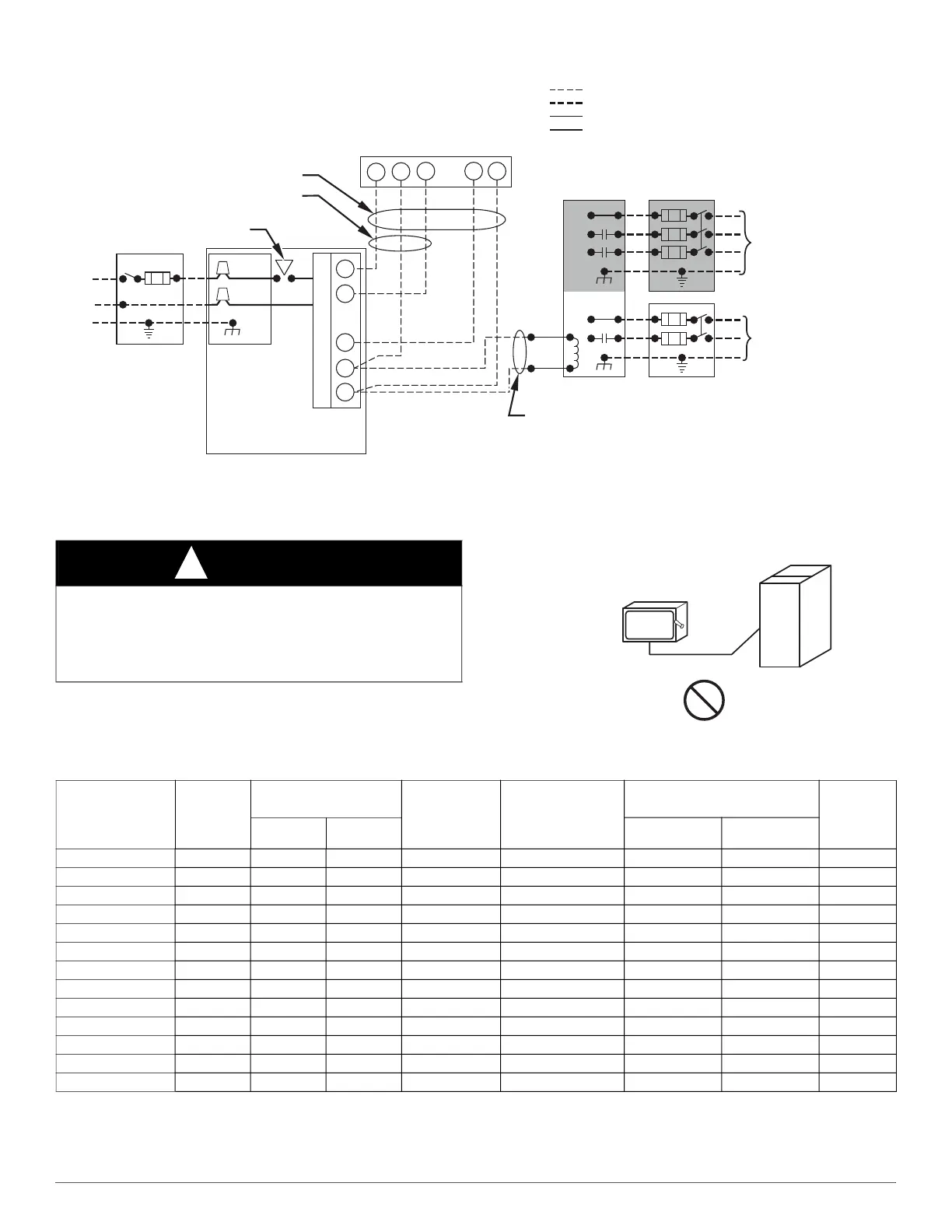
Fig. 24 – Heating and Cooling Application Wiring Diagram with 1-Stage Thermostat
\
A190279
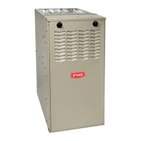
Fig. 25 – Field-Supplied External Electrical Box on Furnace Casing
* Permissible limits of the voltage range at which the unit operates satisfactorily.
# Unit ampacity = 125 percent of largest operating component’s full load amps plus 100 percent of all other potential operating components’ (EAC, humidifier, etc.) full load amps.
† Time-delay type is recommended.
‡ Length shown is as measured one way along wire path between unit and service panel for maximum 2 percent voltage drop.
115-V FIELD-
SUPPLIED
DISCONNECT
AUXILIARY
J-BOX
24-V
TERMINAL
BLOCK
THREE-WIRE
HEATING-ONLY
FIVE WIRE
NOTE 1
NOTE 2
FIELD-SUPPLIED
DISCONNECT
CONDENSING
UNIT
TWO
WIRE
FURNACE
C
O
N
T
R
O
L
R
G
COM
WCR GY
GND
GND
FIELD 24-V WIRING
FIELD 115-, 208/230-, 460-V WIRING
FACTORY 24-V WIRING
FACTORY 115-V WIRING
208/230- OR
460-V
THREE
PHASE
208/230-V
SINGLE
PHASE
BLOWER DOOR SWITCH
WHT
BLK
WHT
BLK
NOTES: Connect Y-terminal in furnace as shown for proper blower operation.
Some thermostats require a "C" terminal connection as shown.
If any of the original wire, as supplied, must be replaced, use
same type or equivalent wire.
W
Y
GND
THERMOSTAT
TERMINALS
1.
2.
3.
WARNING
!
FIRE HAZARD
Failure to follow this warning could result in personal injury, death, or
property damage.
Do not connect aluminum wire between disconnect switch and furnace.
Use only copper wire (see Fig. 25).
COPPER
WIRE ONLY
ELECTRIC
DISCONNECT
SWITCH
ALUMINUM
WIRE
Table 7 – Electrical Data
Unit Size
Volts-
Hertz- Phase
Operating Voltage* Range
Unit
Ampacity#
Minimum Wire
Size AWG
Maximum Wire
Length
‡
Maximum
Fuse
or CKT
BKR Amps
†
Maximum Minimum feet m
36045E14 115-60-1 127 104 7.8 14 47 14.3 15
36045E17 115-60-1 127 104 10.3 14 36 11 15
36070E14 115-60-1 127 104 7.8 14 47 14.3 15
36070E17 115-60-1 127 104 7.8 14 47 14.3 15
48070E17 115-60-1 127 104 14.3 14 25 7.6 15
48070E21 115-60-1 127 104 13.3 14 27 8.2 15
42090E17 115-60-1 127 104 11 14 33 10.1 15
48090E21 115-60-1 127 104 11 14 33 10.1 15
60090E21 115-60-1 127 104 16.9 12 34 10.4 20
60090E24 115-60-1 127 104 13.5 14 27 8.2 15
60110E21 115-60-1 127 104 17.4 12 33 10.1 20
60110E24 115-60-1 127 104 14 14 26 7.9 15
60135E24 115-60-1 127 104 14 14 26 7.9 15