20
Status Codes
Unit may occasionally become unresponsive due to certain
combinations of previous fault codes. There may not be
anything wrong with the unit or components. The unit may
require a high voltage power cycling for at least 2 minutes or
longer to clear the condition. If the condition persists, conduct
further troubleshooting per Service Manual.
ATTENTION
!
Table 7 shows the status codes flashed by the amber status light.
Most system problems can be diagnosed by reading the status code
as flashed by the amber status light on the control board.
The codes are flashed by a series of short and long flashes of the
status light. The short flashes indicate the first digit in the status
code, followed by long flashes indicating the second digit of the
error code.
The short flash is 0.25 seconds ON and the long flash is 1.0 second
ON. Time between flashes is 0.25 seconds. Time between short
flash and first long flash is 1.0 second. Time between code
repeating is 2.5 seconds with LED OFF.
Codes are easily read from user interface (UI)
EXAMPLE:
3 short flashes followed by 2 long flashes indicates a 32 code.
Table 7 shows this to be low pressure switch open.
Status Code Recall Mode
Active status codes are stored in memory even when power is
absent. The most recent flashing status code (highest priority
active) can be recalled from memory via Status Code Recall Mode
and displayed using the amber LED. The Status Code Recall
Mode is accessed by shorting (use a clip wire) the “force defrost”
connector (labeled J2 on the board) and then power ON the unit.
Please make sure the unit is turned OFF before shorting the pins.
Status Code Recall Mode will continue as long as the “force
defrost” terminals remain shorted. The unit will not attempt to heat
or cool while the terminals remain shorted. Once the status code is
read, power--down the unit and remove the short.
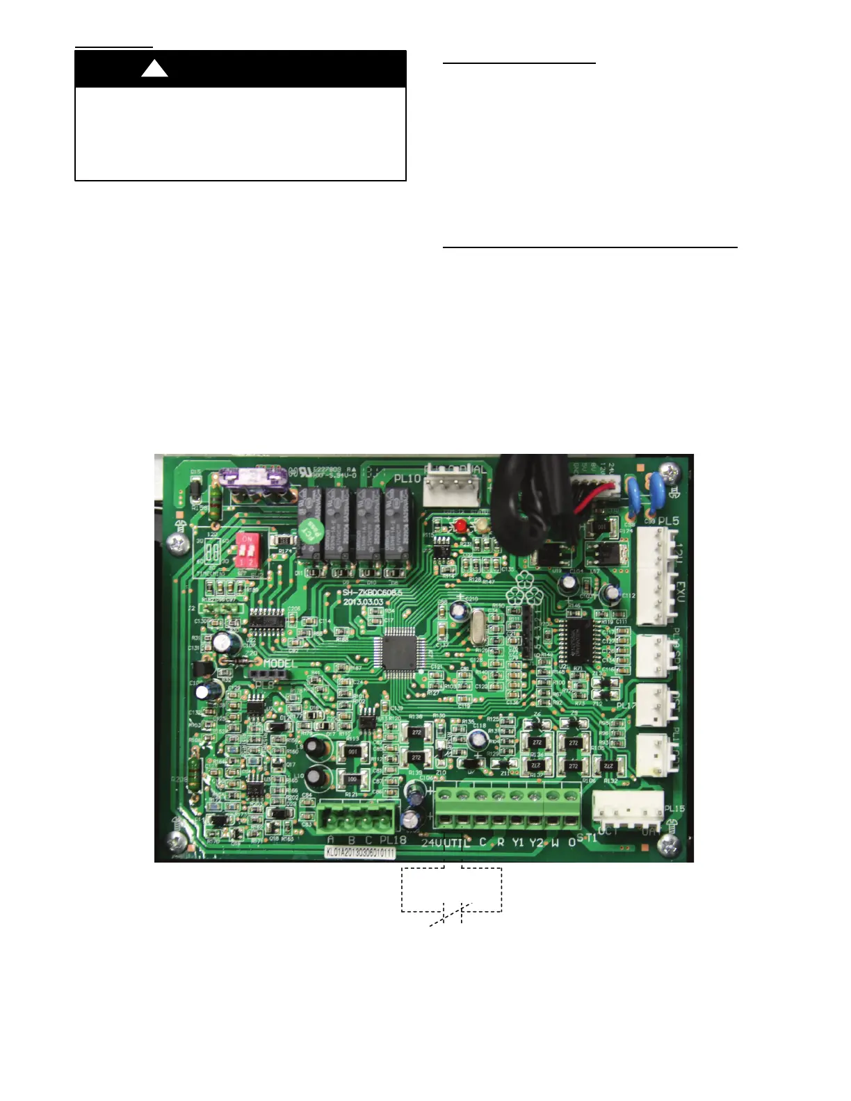
Utility Interface With Evolution Connex Control
The utility curtailment relay should be wired between the two
UTIL connections on the control board for this Evolution
Communicating System (see Fig. 41). This input allows a power
utility device to interrupt compressor operation during peak load
periods. When the utility sends a signal to shut the system down,
the User Interface status screen will display , ”Curtailment Yes”.
See UI installation instructions for setup details.
Utility Relay
A13414
Fig. 41 -- Variable Speed Control Board with optional Utility Relay