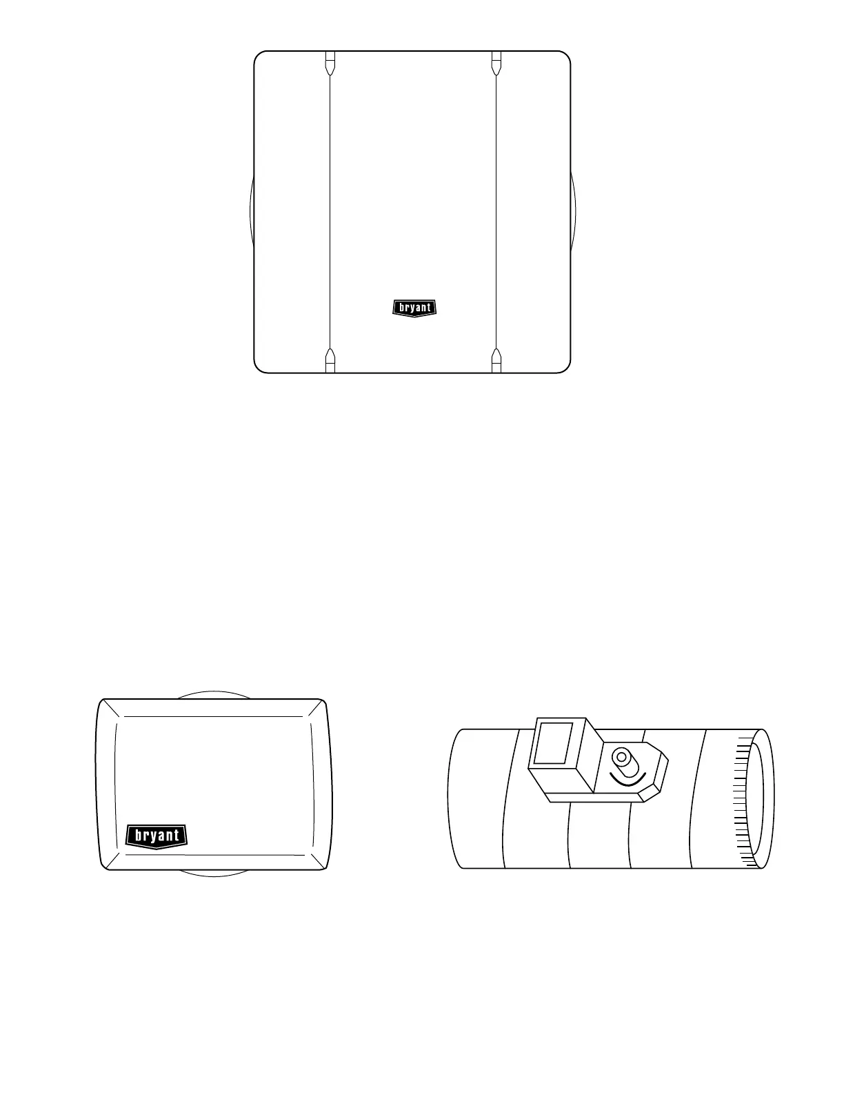
B. Equipment Controller
The Equipment Controller, shown in Fig. 2, is essentially a
junction box for connecting all of the temperature sensor inputs,
and all of the outputs to the zone dampers and to the heating and
cooling equipment. It contains circuits and relays that provide
control of the zoning system, as well as control of the heating and
cooling equipment. The Equipment Controller operates under the
control of the User Interface.
C. Zone Sensors
Zone Perfect Plus kits include Remote Sensors. Optional Smart
Sensors also are available for use with the Zone Perfect Plus
system. Each of these types of sensors is described below.
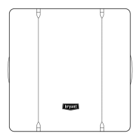
REMOTE SENSORS
Remote Sensors, shown in Fig. 3, are used to measure the
temperature in each zone. A Remote Sensor does not provide a
means to view or adjust the zone temperature; the User Interface
provides a means to view and adjust temperatures for all zones.
SMART SENSORS
The Smart Sensor measures and displays the temperature in the
zone. It also provides a means to adjust the temperature in that
zone only.
D. Equipment Sensors
The following equipment sensors are used in Zone Perfect Plus
installations:
• Zone Perfect Plus installations must include a LAT (leaving
air temperature) sensor.
• If the installation includes a heat pump, an HPT (heat pump
temperature) sensor also must be installed.
•AnODT (outdoor temperature) sensor is optional in most
applications.
For more information about equipment sensors, see the section
"Components Required for Specific Applications."
E. Zone Dampers
Each zone must have at least 1 zone damper, shown in Fig. 4. If
more than 1 duct serves a single zone, up to 3 dampers may be
wired in parallel to a single output on the Equipment Controller.
Each zone damper is operated by an electric motor actuator, which
receives signals from the Equipment Controller. Dampers have 15
positions, ranging from fully closed to fully open. The position
selected for each damper at any given time is based on the relative
conditioning needs of each zone in the current mode.
DESIGNING A ZONE PERFECT
PLUS
INSTALLATION
The main objective when designing a zoning system is to maintain
at least the minimum airflow through the system when only 1 zone
requires conditioning, yet still provide sufficient airflow when all
zones require conditioning. The tasks described below provide
step-by-step instructions for designing an effective zoning system.
These tasks are grouped into the following phases:
Fig. 2—Equipment Controller
A98338
Fig. 3—Remote Sensor
A98339
Fig. 4—Zone Damper
A98340
—4—