NOTE: Read the entire instruction manual before starting the
installation.
This symbol → indicates a change since the last issue.
TABLE OF CONTENTS
PAGE
Safety Considerations.....................................................................1
Installation Considerations.............................................................1
Introduction ....................................................................................1
Installation...................................................................................1-4
Sequence Of Operation...............................................................4-7
Thermostat Wiring......................................................................6-8
Care And Maintenance ..................................................................8
Troubleshooting ........................................................................9-11
Wiring Diagrams.....................................................................12-16
Wiring Diagram Notes.................................................................16
SAFETY CONSIDERATIONS
Improper installation, adjustment, alteration, service, maintenance,
or use can cause fire, electrical shock, or other conditions which
may cause personal injury or property damage. Consult a qualified
installer, service agency, or your distributor or branch for infor-
mation or assistance. The qualified installer or agency must use
factory-authorized kits or accessories when modifying this prod-
uct. Refer to the individual instructions packaged with the kits or
accessories when installing.
Follow all safety codes and wear safety glasses. Have fire
extinguisher available. Read these instructions thoroughly and
follow all warnings or cautions attached to the unit. Consult local
and state building codes and Sheet Metal and Air Conditioning
National Association (SMACNA) for special installation require-
ments.
Recognize safety information. This is the safety-alert symbol
.
When you see this symbol on the unit or in instructions and
manuals, be alert to the potential for personal injury.
Understand the signal words DANGER, WARNING, or CAU-
TION. These words are used with the safety-alert symbol. DAN-
GER identifies the most serious hazards which will result in severe
personal injury or death. WARNING signifies hazards which
could result in personal injury or death. CAUTION is used to
identify unsafe practices which would result in minor personal
injury or product and property damage.
INSTALLATION CONSIDERATIONS
1. Install in non-condensing area with ambients between 32°F
and 150°F.
2. Use vibration isolators (flex connectors) on zone dampers
and ductwork to minimize noise.
3. Place dampers away from areas that may be noise sensitive.
4. TXV is required in air conditioning and heat pump appli-
cations.
5. Use separate isolated transformer to supply power to Zone
Perfect Two-Zone Center. (40va minimum, class 2, trans-
former, field supplied)
6. Load calculations must be performed to determine equip-
ment size. Equipment selection is matched to block load. It
is imperative equipment is not over sized.
7. Ductwork must be designed based off the sum of peak plus
25 percent oversize. It is imperative ductwork is not under
sized.
INTRODUCTION
The Zone Perfect Two-Zone System allows the air conditioning
and heating equipment to control temperatures in 2 distinct spaces
or zones within a building. Each zone has independent temperature
settings controlled by a thermostat.
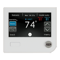
NOTE: Thermostats are purchased separately.
The comfort temperature settings can change automatically
through the use of schedules if programmable thermostats are
selected. This allows Zone Perfect Two-Zone to change the
temperature settings in zones to reflect occupancy or usage. The
Zone Perfect Two-Zone System uses motorized air volume control
dampers (also called zone dampers) to regulate the flow of
conditioned air into the zones.
INSTALLATION
I. CHECK EQUIPMENT AND JOBSITE
A. Inspect Equipment
File claim with shipping company, prior to installation, if shipment
is damaged or incomplete.
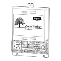
Fig. 1—Zone Perfect Two-Zone System
(Shown Without Cover)
A97291
3
WARNING!
Rev
HOT parts
under this label
Y1
W1
W2
W1
W2
G
RH
RC
B
O
Y2
Y1
Equipment Term.
Sensors
HP
Duct
C1
Z
o
n
e
1
Z
o
n
e
2
Op
C
C1
Op
C
Emergency
Heat
RC-RH
Jumper
Y2
G
On
Off
24 VAC
R
W1W2 C
G
Y2
Y1
Y2
Y1
R
W1
W2
C
Equpimt
DTO
Fnc Ht
w/oF
w/F
On
Off
HP
Fnc
T'stat
Fnc
HP
®
installation instructions
ZONE PERFECT™
TWO-ZONE
Cancels: II ZONEKIT-0-2 II ZONEKIT-0-6
6-97
ZONEKIT
—1—
→
→