MAXIMUM CYCLE RATE
The Zone Perfect Two-Zone will allow a maximum of 4 equip-
ment cycles per hr or 1 every 15 minutes when a heating or cooling
mode is activated. When a demand exists, and internal timer will
start counting down 15, 14, 13...0 minutes. Once the timer expires
the control will allow a new mode to restart the equipment. The
internal time, as well as the cooling 5-minute timeguard can be
cleared by using the comprotec override feature.
CARE AND MAINTENANCE
For continuing optimum performance and to minimize possible
equipment failure, it is essential that periodic maintenance be
performed on this equipment. Consult your servicing contractor for
the proper frequency of maintenance. Frequency may vary depend-
ing upon geographic areas.
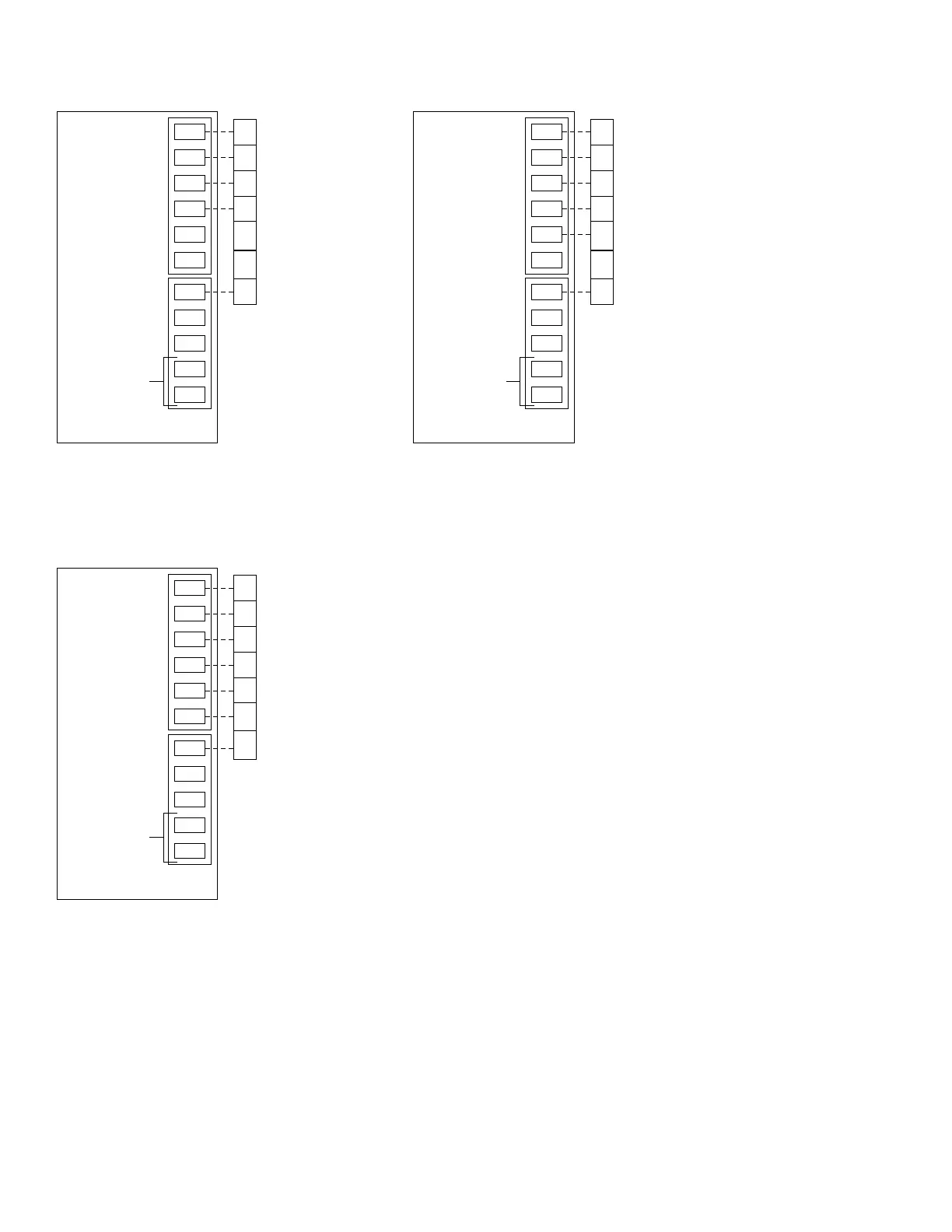
→ Fig. 14—Electronic Programmable Thermostat Wiring Diagrams
A97295
W
/W1
Y1
/W2
G
R
Y
/Y2
COOL STAGE 1
PROGRAMMABLE
ELECTRONIC
THERMOSTAT
MODEL 2S
TWO-ZONE BOARD
THERMOSTAT
INPUT
FAN
HEAT STAGE 1
COOL STAGE 2
HEAT STAGE 2
24 VAC HOT
24 VAC COMM
N/A
TROUBLE
OUTDOOR
SENSOR
CONNECTION
TWO-STAGE HEAT,
TWO-STAGE COOL
SEE NOTES 1, 2, AND 3
O
/W2
B
C
G
Y1
W1
Y2
R
C
L
S1
S2
W2
*
W
/W1
G
Y
/Y2
O
/W2
Y1
/W2
R24 VAC HOT
TWO-ZONE BOARD
THERMOSTAT
INPUT
FAN
HEAT STAGE 1
COOL STAGE 1
HEAT STAGE 2
N/A
24 VAC COMM
N/A
N/A
OUTDOOR
SENSOR
CONNECTION
TWO-STAGE HEAT,
SINGLE-STAGE COOL
SEE NOTES 1, 2, AND 3
B
C
G
R
W1
Y1
W2
Y2
C
L
S1
S2
*
W
/W1
G
Y
/Y2
O
/W2
Y1
/W2
R24 VAC HOT
PROGRAMMABLE
ELECTRONIC
THERMOSTAT
MODEL AC
PROGRAMMABLE
ELECTRONIC
THERMOSTAT
MODEL HP
TWO-ZONE BOARD
THERMOSTAT
INPUT
FAN
HEAT STAGE 1
COOL STAGE 1
N/A
N/A
24 VAC COMM
N/A
N/A
OUTDOOR
SENSOR
CONNECTION
SINGLE-STAGE HEAT,
SINGLE-STAGE COOL
SEE NOTES 1 AND 3
B
C
G
R
W1
Y1
W2
Y2
C
L
S1
S2
*
WIRING DIAGRAM NOTES:
* Hook up G on zone 1 thermostat only.
Set thermostat dip switch A to ON.
Set thermostat dip switch C to ON. This will disable
timeguard and cycle protection in thermostat by setting
it to ZONE mode. Refer to thermostat Installation Instructions
for details on how to do this.
1.
2.
3.
—8—