CONNECTING
BRYSTON
BP20/25
PREAMPLIFIERS
FOR
OPTIONAL
POWER
ON/OFF
FUNCTIONS
The
Bryston
MPS-1
power
supply
(supplied
with
all
Bp20/25
preamps)
has
two
ways
of
being
turned
on and
two
ways
of
turning
on
other
equipment
(such as
Bryston
power
ampli-
fiers)
.
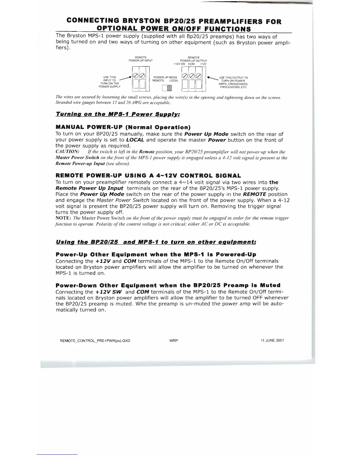
RE
MO
TE
POWE
R-U
P INPUT
+
12
V
SW
POW
R
EM
O
TE
OU
C
OM
ER-UP TPUT
+1
2V
"
""
'""
~
1
0
1
011
e
~
"",
MO
",
1
DDD
1
0
1
011~
",
UH
O",Mm
DD REMO
TE
0
INPUT TO LOCAL TU
RN
ON PO
WE
R
TU
RN
ON
THE
AM
PS, CROSSOVE
RS
,
PO
W
ER
SUPPLY P
RO
CESSO R
S,
ETC
c.u
Th
e wires are secured by loosening
th
e small screws, placing
th
e w
ire
rs)
in
th
e opening and
ti
ghtening down on
th
e screw
s.
Stranded wire gauges beMeen 12 and 26 A
we
ar
e acceptable..
Turning
on
the
MPS-1
Power
Supply:
MANUAL
POWER-UP
(Normal
Operation)
To
turn
on
your
BP20/25
manually,
make
sure
the
Power
Up
Mode
switch
on
the
rear
of
your
power
supply
is
set
to
LOCAL
and
operate
the
master
Power
button
on
the
front
of
the
power
supply
as
required.
CA UTION:
If
th
e switch
is
le
ft
in
th
e Remote position, your
BP
20125
pr
eamplifier will not
po
wer-up when
th
e
Master Power Switch on
th
e front
of
th
e MPS
-J
po
we
r supply is engaged unless a
4-/2
volt signal is p
re
sent
at
th
e
Remote Power-up
Input
(s
ee abo
ve)
.
REMOTE
POWER-UP
USING
A
4-12V
CONTROL
SIGNAL
To
turn
on
your
preamplifier
remotely
connect
a
4",
14
volt
signal via
two
wires
into
the
Remote
Power
Up
Input
terminals
on
the
rear
of
the
BP20/25's
MPS-1
power
supply.
Place
the
Power
Up
Mode
switch
on
the
rear
of
the
power
supply
in
the
REMOTE
position
and engage
the
Master
Power
Switch
located on
the
front
of
the
power
supply. When a
4-12
volt
signal is
present
the
BP20/25
power
supply
will
turn
on.
Removing
the
trigger
signal
turns
the
power
supply
off.
NOTE:
The Master Power Switch on
th
eji-ont
of
th
e power supply must be engaged
in
order f or the remote trigger
lim
ction
to
operate. Polarity
of
th
e control voltage is not critical; either AC or DC is acceptable.
UsIng
the
BP20125
and
MPS-1
to
turn
on
other
equIpment:
Power-Up
Other
Equipment
when
the
MPS-1
Is
Powered-Up
Connecting
the
+12Vand
COM
terminals
of
the
MPS-1
to
the
Remote
On/Off
terminals
located on
Bryston
power
amplifiers
will
allow
the
amplifier
to
be
turned
on
whenever
the
MPS-1 is
turned
on.
Power-Down
Other
Equipment
when
the
BP20/25
Preamp
Is
Muted
Connecting
the
+12V
SW
and
COM
terminals
of
the
MPS-1
to
the
Remote
On/Off
termi-
nals located on
Bryston
power
amplifiers
will
allow
the
amplifier
to
be
turned
OFF
whenever
the
BP20/25
preamp
is
muted.
Whe
the
preamp
is
un-muted
the
power
amp
will be
auto-
matically
turned
on.
REMOTE_CONTROL_PRE+PWR(ps).QXD
WRP
11
JUNE 2001