GENERAL
INSTRUCTIONS
Setup Recommendations:
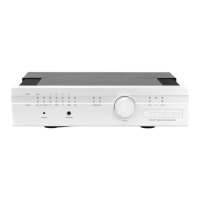
. Congratulations
on
your purchase
of
a Bryston
preampltfler. We are confident it will provide you with
many years
of
musical enjoyment.
You may place your preamplifier
in
any conve-
nient location, with two possible exceptions.
If
you
own
the Bryston BP-25 remote-control version, positJon the
preamplifier to maintain a direct line-of-sight between the
hand-held remote and the remote s
ensor
eye located
on
the left side
of
the preamplifier's front panel.
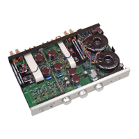
If
you purchased the BP-25P
or
BP-25MC,
whICh
includes a
Phono
section, avoid placing the pream-
plifier directly on top
of
your
power
amplifier.
Power
amplifiers usually employ large power supplies and the
transformer
(s)
in
the power supplies can cause interfer-
ence Qlwn) with the sensitive
phono
section inside the
preamp
The
BP-PS outboard
power
supply provides AC
power for tile BP-20 and BP-25 preamplifiers. It has a
slide power switch located
on
the front and a green
LED
to indicate power on.
On the rear
of
the wlit
is
a three-position con-
nector which provides a control voltage for remote turn
on
/o
ff of your Bryston
THX
amplifier
(s)
or
other ampli-
fier
s so equipped. This feature can be used
in
tw
o ways
depending
on
the wiring arrangement utilized:
Option
one
provides for the preamplifier and
power amplifier to be turned
on
or
off
when
you
operate the power switch located on the front
of
the
external power supply.
TUOling the
power
off
with the
switch
on
the outboard
power
supply removes
AC
power
Cormect the preamplifier's left and right outputs
from either the RCA
or
Balanced
XLR
connectors to the
appropriate left and right input jacks
on
your power
amplifier. Balanced cables are an advantage
if
you are
using long
fW1
S
of
cable, (greater than 20 feet), between
your preamplifier and
power
amplifier.
Cormect your
CD
player, tlli1er, tape deck., video
recorder, or laser disc, etc. to the specific left/ right pream-
plifier inputs With
phono
-e
quipped models, (BP-25P
or
BP-:?5MQ,
COlU1ect
your
phono
cables to the
phono
input lacks
If
your turntable leads have a separate
groW1d
wire, it may be cormected to the groW1d lug adjacent to
the phono mputs
on
the rear panel.
Next, insert the 5-pin din cable from the out-
board
power
supply into the
input
cormector located
on
the rear
of
the preamplifier.
Then
plug the
power
supply
into an appropriate AC
power
outlet.
The
preamplifier
is
powered up by engaging the slide switch located
on
the
front
of
the external power supply.
The
"
green"
LED
on
the outboard
power
supply and the preamplifier front
panel indicates power-on.
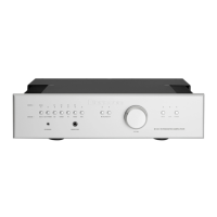
If
the preamplifier has
been
placed in the "mute"
position operating the
volume
up button on the
remote will automatically
uo-mute
the BP-25 pream-
plifier, turning the
LED
from red to green.
On
the
BP-20 you
must
manually activate the
mute
toggle
on
the front panel. Both the Mute switch and the
Polarity Invert switch are momentary-toggle types, oper-
ated by push-and-release.
BP-PS Power Supply:
from both the preamplifier and the
power
amplifier
(s)
for
complete system shut-down.
Option two allows the
power
amplifier(s)
to
be turned on or
off
with the
mute
button
on
the
haud-held remote control unit
or
the
mute
toggle
on
the front panel
of
the preamplifier.
TIUs
will
shut
down
your system 'for the night', completely removing power
from the amplifiers,
but
leaving the preamp
in
the
Mute/
standby mode, indicated
by
the red
LED
on
the preampli-
fier's fron t panel.
Please refer to the diagram
on
the included
separate instruction sheet for further clarity and optional
WlfU1g
arrangements.
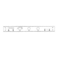
Connections:
The
Bryston BP-20
and
BP-25 preamps also
feature two pairs
of
balanced
XLR
input jacks. Many
signal sources, including CD-players and separate D / A
converters are
now
available with Balanced outputs for
minimwn
noise pickup
on
the cables.
The
tape loop may be used
to
insert a surroW1d
sO
Wld
processor, cassette tape
deck
or
video tape recorder
into your
sys
tem.
Plug
your tape deck
or
external proces-
sor's i.nput cables into the
'To
Tape'
jacks, and the proces-
sor
or
deck's
output
cables into the '
From
Tape
' lacks at
the rear
of
the preamp.
The
tape
or
processor loop may
be operated via the toggle switch located
on
the front
panel
of
the preamplifier.
Page 2
 Loading...