Do you have a question about the Bryston BHA-1 and is the answer not in the manual?
Opening remarks thanking the user and outlining the purpose of the manual.
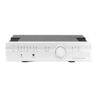
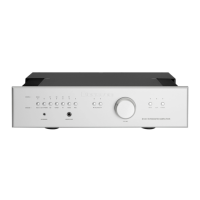
Details the key features of the BHA-1 headphone amplifier.
Provides guidance on the proper installation and placement of the unit.
Recommendations for using power conditioners with the BHA-1.
Explains the non-locking XLR connectors and special order options.
Information regarding the fuse type and location within the unit.
Selects between Balanced (XLR), RCA (unbalanced), and MINI (3.5mm) input types.
Allows selection between 14dB (gain=5) or 20dB (gain=10) settings.
Primary control for adjusting the output audio volume.
Adjusts the audio balance between the left and right channels.
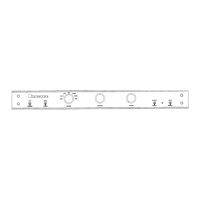
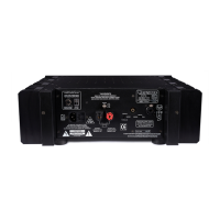
Dual 3-pin XLR connectors for left and right channel balanced outputs.
A single 4-pin XLR connector for balanced output, parallel to dual 3-pin XLRs.
A 1/4 inch stereo phone jack for single-ended or unbalanced output.
Indicates unit status: green for ON, red for external power availability.
Main power switch; UP is ON, DOWN is OFF. No standby mode.
Standard C14 inlet for connecting the AC power cord.
Houses the fuse; requires disconnecting power before access.
Provides warnings and cautions related to the fuse.
Input for remote power ON/OFF control using 12V DC.
3.5mm jack for connecting audio sources like MP3 players.
RCA jacks for connecting unbalanced analog audio inputs.
3-pin female XLR jacks for connecting balanced analog audio inputs.
Contains model, serial number, and manufacturing date code information.
| Type | Headphone Amplifier |
|---|---|
| Frequency Response | 20 Hz to 20 kHz ±0.1dB |
| Input Impedance | 50kΩ |
| Inputs | 2x XLR, 2x RCA |
| Outputs | 4-pin XLR, 1/4 inch TRS |
| Gain | 20dB high gain |
| Total Harmonic Distortion | Less than 0.005% |
| THD+N | Less than 0.005% |