BHA-1 HEADPHONE AMPLIFIER
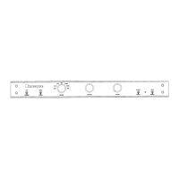
INPUT (BHA-1)
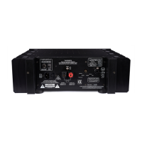
OUTPUT (MPS-2)
CONNECTING THE BHA1...EXT HEADPHONE AMPLIFIER
to the
MPS-2 POWER SUPPLY
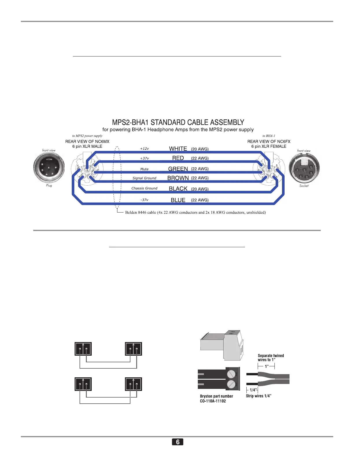
The BHA-1 is available without an internal power supply. These models require a Bryston MPS-2 ex-
ternal power supply and an interconnecting cable as shown below. The required cable assembly is with
the MPS-2.
When the MPS-2 is properly connected to the BHA-1 and the MPS-2 is turned on but the BHA-1 is
turned off, the BHA-1’s front panel status indicator LED will light red. This indicates that power is avail-
able to the BHA-1. Once the BHA-1 is turned on, either by the front panel On/Off switch or remotely by
via the Remote Trigger connection, the LED will light green.
REMOTE TRIGGER HOOKUP
When the front panel power switch (item #9) is turned off (down) the unit can still be powered on by ap-
plying 12 volts DC at 50mA, across the two TRIGGER INPUT pins. Because the Remote Trigger Input
is rectified and regulated the polarity of the this input voltage doesn’t matter. The Trigger voltage can
be supplied form Bryston’s MPS-2 External Power Supply, from another piece of Bryston equipment
with remote trigger capability or from another source. A two position mating screw terminal connector
(Bryston part number CO-110A-11102) is included with each unit. Do not over tighten the terminal set
screws as this can actually cause the connection to loosen over time. Maximum torque is 4.5 inch-
pounds (0.5Nm). Stranded copper wire between 24 and 18 AWG is recommended. Strip 1/4” of insu-
lation off the end of the wires to be connected to the CO-110A-11102. The wire ends should be bare
copper; not tinned.
The Remote trigger input is non-polarized so
either output wire can go to either input pin.
Tighten wires with no more than 0.5Nm torque