Fi
. 2
. Rear
hain ad
uster.
Fig. 27. Front chain adjuster
TRANSMISSION
Adjustments which can be carried out without dismantling
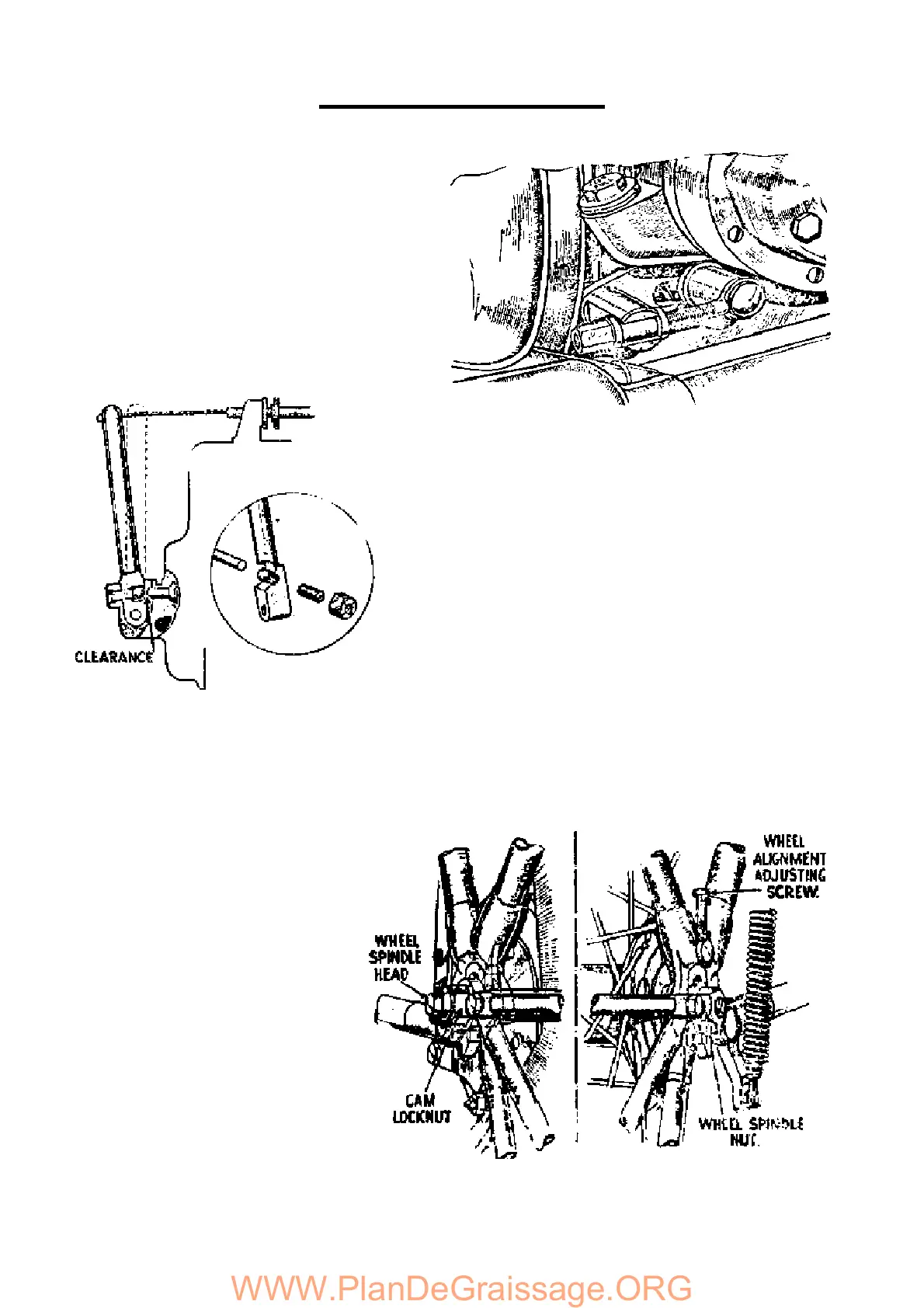
CLUTCH ADJUSTMENT
Two adjustments are provided at the clutch control
arm on the gearbox outer cover. The adjustment,
which is for the clutch push rod will be exposed when
the rubber cover at the base of the arm is moved
aside and consists of a grub screw and locknut.
Between the inner end of the screw and the clutch
push rod a steel ball is inserted and the grub screw
must be adjusted so that there is just a little
clearance between the ball and push rod. The
control arm in the declutched position should be as
upright as possible.
Fig. 26. Clutch control adjustment.
The second adjustment is for the cable itself. If the
control arm has been set in a new position, the cable
length is altered to suit by means of the thumb nut on
the cable stop above the gearbox.
FRONT CHAIN ADJUSTMENT
The front chain is adjusted by moving
the gearbox. The latter slides between
two plates and cannot, therefore, cause
chain misalignment.
Release the gearbox fixing bolts and
move the box by means of the screw
adjuster (see Fig. 27) until the chain
has about ½ “ total play at a point about
mid-way between its sprockets. The chaincase filler
plug can be used as an inspection cover for this
purpose, or alternatively, the chaincase outer cover
can be taken off. Make sure that the adjustment is
correct for all positions of the sprockets and that the
gearbox bolts are well tightened.
REAR CHAIN ADJUSTMENT
The rear chain is tensioned by means of a special
cam on the nearside of the wheel spindle and by
screw adjustment on the offside. First, release the
offside spindle nut (see Fig. 28), then the cam
locknut on the nearside. The latter nut is the larger of
the two nuts on this side. Then, applying a spanner
to the smaller nut, turn it in an anti-clockwise
direction to tighten the chain, until it has a total
amount of play, mid-way between the sprockets, of
about ¾ “.
20