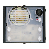
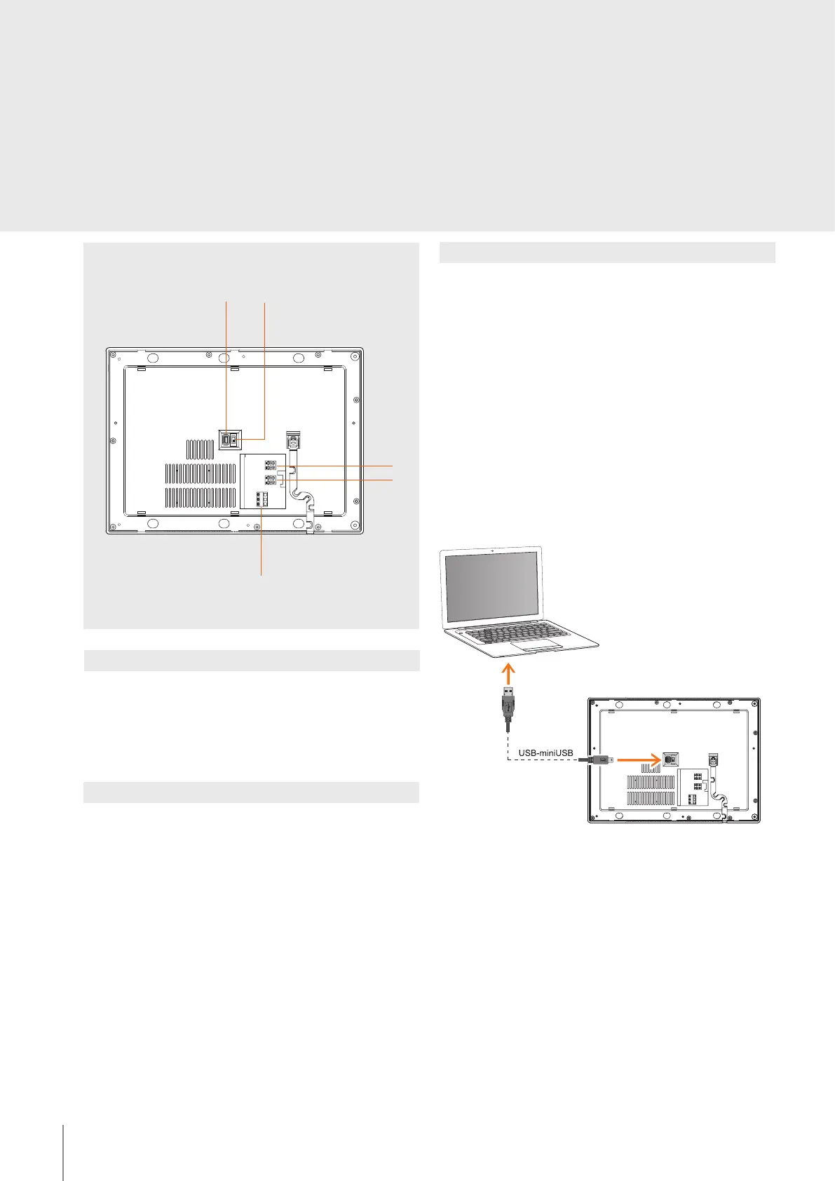
Legend
1. Mini-USB connector for PC connection
2. Line termination ON/OFF micro-switch
3. Clamps for the connection of the 2-WIRE SCS BUS BTicino
4. Additional power supply connection clamps (1 - 2)
5. Clamps for the connection of the power supply of the audible signal device
(optional)
1
2
3
4
5
Rear view
Conguration
The switchboard must be configured as far as:
- Setting of the local switchboard address (0 or 1 - 15)
- Setting of the associated entrance panel address (1 - 80)
- Setting of any associated service handset
Two different configuration modes are available:
- directly from the icon menu of the switchboard
-
using a PC with the TiSwitchboardDevice software installed (available in the CD supplied)
WARNING: certain specific functions, such as the filling of the directories and the
management of the ringtones, require the configuration to be performed using the PC.
To transfer the conguration performed using the software or to update the device,
connect the switchboard to the PC using the USB-mini cable.
Functional notes
The maximum installation distances are the same as for 2 WIRE handsets.
Calls from entrance panels are received by all switchboards connected to the system
(the rst switchboard answering takes the call).
Calls from handsets may be managed in two dierent ways (based on the conguration
of the handsets themselves):
mode 1 – handsets congured with P=0 – the calls from these handsets are received
by all the switchboards of the system (the rst switchboard answering takes the call).
mode 2 – example, Handset congured with P=81 – the calls from these handsets
are only received by the secondary switchboard congured with 1; handsets congured
with P=95 – calls from these Handsets are only received by the secondary handset
congured with 15.
The management of the operating mode (day/night) is only entrusted to the main
switchboard (congured with 0).
To enable communication the device must be powered.
2
BT00412-c-UK
346310
 Loading...