Wiring diagrams
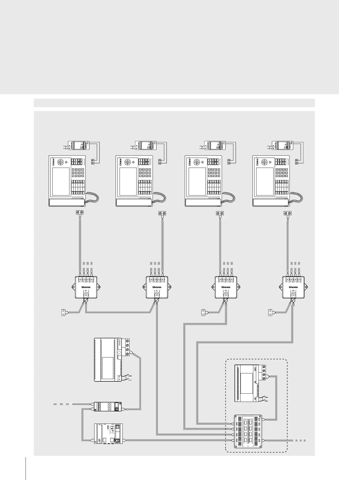
Diagram 4: 2 wire backbone connection of 16 switchboards
BUS 2 1
SC S
OUT1 OUT2 OUT3 OUT 4
IN1IN2
IN3
IN4
OUT
IN
230V a.c .
F441
346000
230 Vac
2 1
BUS
346310
346020
230 Vac
2 1
BUS
346310
346020
230 Vac
2 1
346310
346020
230 Vac
2 1
346310
346020
ON
OUT
IN
ON OFF
BUS 2 1
PS
BUS
TK
BUS
PI
230 Vac
BUS
BUS
346000346850
346841
346841
346841
346841
346830
3499
3499
3499
Main EP
(P = 1)
To Handsets
riser 1
Main switchboard = 0
Secondary switchboard = 12
Secondary switchboard = 8
Secondary switchboard = 7
Switchboard 1
Switchboard 2
Switchboard 3
Switchboard 13
Switchboard 14
Switchboard 15
Switchboard 4
Switchboard 5
Switchboard 6
Switchboard 9
Switchboard 10
Switchboard 11
NOTES:
– In systems with several switchboards, secondary
switchboards must be powered locally with an
additional power supply item 346020.
– For the configuration of the switchboard refer to
the documentation supplied with the product
6
BT00412-c-UK

 Loading...