N°
AUX
MOD
T - C + -
NC pushbutton
230 Vac
1- 2
2 1
ON
346851
ON
OFF
M
3
5
346851 346851
ON
346851
ON
OF F
BUS 2 1
SC S
OUT1 OUT2 OUT3 OUT 4
IN1IN2
IN3
IN4
OUT
IN
230V a.c .
F441
346000
M
1
5
MO D
MO D
OFFON
OFFON
ON
346851
ON
OFF
M
2
5
346851
MO D
OFFON
BUS
230V a.c .
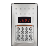
346310
346020
E46ADCN
3480
4615
Alarm reset
NO pushbutton
NC pushbutton
Technical alarm activation
OUT
I N
C
F422
F422
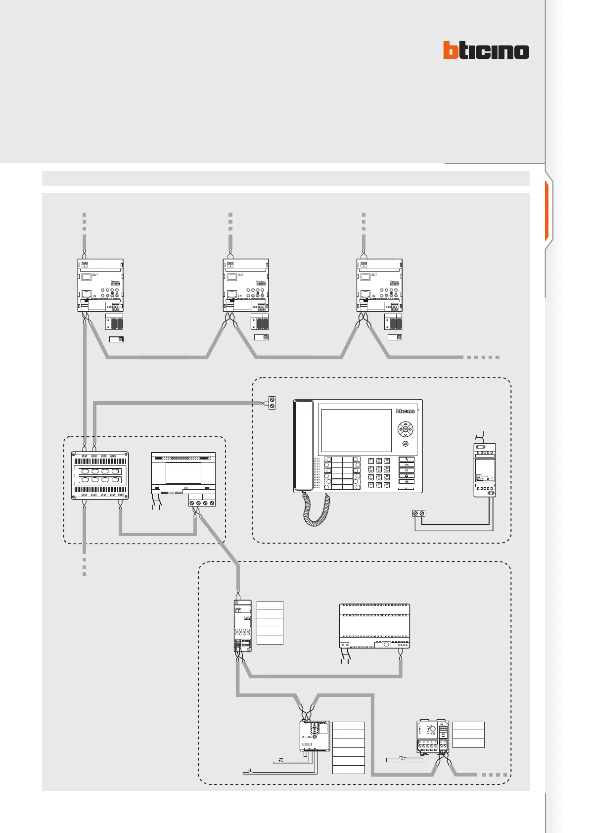
Wiring diagrams
Diagram 5 : Display of alarms from common parts on backbone
NOTES:
– Additional power supply with item 346020
recommended.
– For the functional check and the calculation of
absorptions use the YouDiagram software - which
can be downloaded free of charge from the website
www.international.bticino.com - ASSISTANCE AND
TOOLS - TECHNICAL SOFTWARE.
– For the configuration of the switchboard refer to
the documentation supplied with the product.
– On the common parts it is possible to connect,
using interface item F422, the contact interfaces
for the management of alarms (max. 9 interfaces)
- e.g. door/window contacts and technical alarms
(gas, water, etc.). Refer to the specific MY HOME
documentation.
–
All apartment and common alarms are only managed
by the main switchboard (configured with 0).
Main switchboard conguration = 0
Main EP
(P = 1)
Riser 1 Riser 3Riser 2
N° = 2
AUX = 1-9
MOD = –
Z1 = 9
N1 = 1
MOD1 = –
Z2 = –
N2 = –
MOD2 = 1-9
I1 = –
I2 = –
I3 = –
I4 = 1
MOD = 3
TECHNICAL SHEETS
7
BT00412-c-UK
346310

 Loading...