4
322052
24/03/2016BT00875-a-
323002
BUS
322052 322052
322052 322052
322052 322052
322052 322052
BUS
BUS
BUS
BUS
BUS
BUS
BUS
323002
322011
BUS
323005
PB
D
D
Wiring diagram
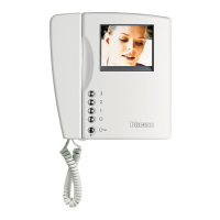
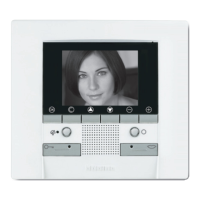
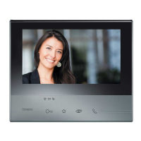
Hands-free colour internal unit
To next
shunt floor
323002
ITEM DESCRIPTION
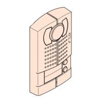
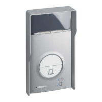
322011 Digital call entrance panel
323005 Main power supply
323010 Auxiliary power supply
323002 Floor shunt
322052 7” Hands-free colour internal unit
L1 Electric door lock 12 V – 4 A
P Impulsive Door lock release
B Pushbutton
S: Configure and insert the jumpers with the
system SWITCHED OFF. Also every time the
configuration is modified the pws must
be switched OFF and ON again, waiting
about 1 minute.
WARNING
A
See next page for configuration
B
To install an alternative Entrance panel,
refer to the wiring variation section.
Device configuration by SF2 software.
C
Set the internal IMPEDANCE SWITCH
to ON.
D
Auxiliary PWS 323010 must be used in
relation with the distance extension -
see specific system section.
EN

 Loading...