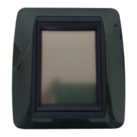
Electronic Control Box
6
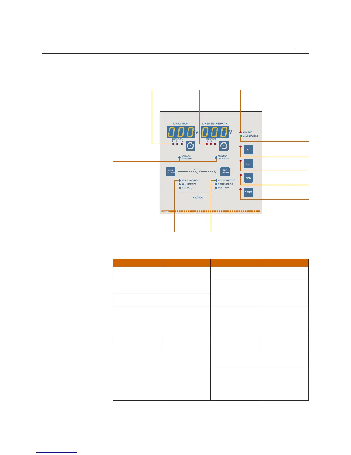
2.3 LEDs
• The front panel has some LEDs which indicate the status of the circuit breakers controlled
by the electronic control box.
LED On Off Flashing
ALARM
No alarm enabled
One or more alarms
enabled (RED)
POWER SUPPLY
Device powered
(GREEN)
No power
OPEN/CLOSE
CONTROL
Close control (RED)
Open control (GREEN)
No control
OPEN/CLOSED
✱
Circuit breaker closed
(RED)
Circuit breaker open
(GREEN)
Auxiliary contacts
not connected
DISCONNECTED
✱✱
Circuit breaker not
inserted in its base
Circuit breaker inserted
or not-inserted-control
disabled
TRIPPED
✱✱
Circuit breaker tripped
Circuit breaker not
tripped or AL contact
not connected
PRESENCE
L1/L2/L3
Voltage present No voltage
1HZ = Time of
presence/absence
in progress
5HZ = Display
measurements
selection
✱ If the auxiliary contacts have been connected, the LED will represent the status of the circuit
breakers, otherwise it will remain off.
✱✱ If the contacts have been connected properly, the LED will represent the status of the circuit
breakers, otherwise the LEDs will remain off.
ALARM LED
(red)
POWER SUPPLY LED
(green)
SET key LED
(red)
AUT key LED
(red)
MAN key LED
(red)
RESET key LED
(red)
Led L1/L2/L3
Presence of
voltage on main
line (red)
Main line /
secondary line
CONTROLS LED
(two-colors)
Status LED,
main line
circuit breaker
Status LED,
secondary line
circuit breaker
Led L1/L2/L3
Presence of voltage
on secondary line
(red)
• The following table describes the meaning of the various LEDs.
Some of them are bicolor and have a different meaning according to the color.
 Loading...